
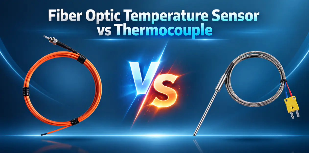
This comparison focuses on fluorescence-based point fiber optic temperature sensors and conventional thermocouples.
Fiber optic temperature sensors and thermocouples can both provide point temperature measurement, but their sensing and signal-transmission methods are very different. A thermocouple generates a small electrical voltage at the junction of two dissimilar metals and transmits that signal through conductive wires. A fiber optic temperature probe uses an optical sensing path and sends the measurement signal through optical fiber.
Thermocouples are widely used for conventional industrial temperature measurement, especially where high temperature capability, simple construction and established instrumentation are important. Fiber optic sensing becomes especially useful where electrical isolation, EMI immunity, non-conductive measurement or strong electromagnetic environments are important.
Key Takeaways
- Thermocouples are widely used for industrial temperature measurement and are available in many probe constructions and temperature ranges.
- Fiber optic probes use an electrically isolated optical signal path instead of conductive measurement wiring.
- High voltage, EMI, RF, microwave and strong magnetic fields can strongly influence sensor selection.
- Thermocouples are often practical for furnaces, machinery, process equipment and conventional industrial measurements.
- Fiber optic sensing is particularly suitable for transformer windings, energized equipment and electrically sensitive measurement points.
- The final choice should consider temperature range, electrical environment, probe geometry, routing distance, channel count and monitoring interface.
Fiber Optic Temperature Sensor vs Thermocouple at a Glance
| Comparison | Fiber Optic Temperature Sensor | Thermocouple |
|---|---|---|
| Measurement Principle | Optical point-temperature measurement | Thermoelectric voltage at a metal junction |
| Signal Path | Optical fiber | Electrical conductive wires |
| Electrical Conductivity | Non-conductive sensing path | Conductive sensing path |
| EMI / RFI Immunity | Optical signal path is inherently immune to EMI along the sensing fiber | Low-level electrical signal may require shielding and correct installation |
| High-Voltage Measurement | Suitable for direct measurement near energized structures | Suitable when insulation and wiring are properly designed |
| Strong Magnetic Fields | Not affected by magnetic field coupling along the fiber | May require additional shielding or routing consideration |
| Typical Temperature Range | Depends on optical probe configuration | Depends on thermocouple type and probe construction |
| Response Time | Small probes can respond quickly | Depends on junction type and sheath diameter |
| Probe Size | Compact sensing tip, varies by configuration | Wide range of constructions, from fine-wire to sheathed probes |
| Long-Distance Signal Routing | Optical fiber routing with electrical isolation | Extension or compensation cable routing |
| Multi-Point Monitoring | Multiple probes connect to a multi-channel instrument | Multiple thermocouples connect to acquisition or PLC systems |
| Signal Conditioning | Requires a fiber optic temperature transmitter or monitoring instrument | Requires cold-junction compensation and acquisition electronics |
| PLC / SCADA Integration | Via RS485, Modbus, analog output or relay from the monitoring instrument | Via thermocouple input module, transmitter or data acquisition unit |
| Typical Applications | Transformer windings, high-voltage equipment, RF/EMI-sensitive locations | Furnaces, ovens, machinery, general industrial measurement |
How the Two Temperature Sensors Measure Temperature
Fiber Optic Temperature Sensor
Light travels through the optical fiber to a defined probe tip, where the sensing takes place. The optical return signal is processed by a monitoring instrument, which converts it into a temperature reading. No electrical measurement signal is required at the sensing point.
Thermocouple
Two dissimilar metals form a measuring junction. A temperature difference across the junction produces a small thermoelectric voltage, an effect known as the Seebeck effect. This signal is carried through conductive thermocouple wires, and measurement electronics convert the signal into a temperature value.
Electrical Isolation and High-Voltage Measurement
This is one of the most important distinctions between the two technologies. A fiber optic probe uses a non-conductive optical sensing path, while a thermocouple relies on a metal junction connected through conductive wires.
This distinction matters in applications such as transformer windings, high-voltage test equipment, switchgear, energized components and high-current equipment. Thermocouples can be used in many electrical applications when insulation, grounding and wiring are properly designed. However, applications requiring a non-conductive measurement path may favor fiber optic sensing.
EMI, RFI and Strong Electromagnetic Fields
Fiber optic signal transmission is inherently immune to electromagnetic interference along the sensing fiber. Thermocouples use low-level electrical signals, so shielding, grounding, cable routing and instrumentation design can become more important in electrically noisy environments.
Typical environments where optical sensing may be preferred include transformer windings, generators, high-current bus systems, RF equipment, microwave heating, MRI systems and high-voltage laboratories.
Temperature Range and High-Temperature Capability
Thermocouples are available in many types, such as Type K, Type J, Type T, Type N, Type R and Type S, and are widely used across broad and often very high temperature ranges depending on thermocouple type and probe construction.
Typical fiber optic probe configurations may cover approximately -40 to 260 °C, depending on probe structure. For very high-temperature industrial processes, certain thermocouple types may offer a wider usable range. For electrically sensitive environments within the supported optical probe range, fiber optic sensing may provide stronger electrical isolation advantages.
Accuracy, Stability and Measurement Quality
Fiber optic probes typically offer accuracy in the region of ±0.5 to ±1 °C, depending on probe and instrument configuration. Thermocouple accuracy depends on the thermocouple type, tolerance class, wire quality, cold-junction compensation, instrumentation and installation.
| Factor | Fiber Optic | Thermocouple |
|---|---|---|
| Sensor Signal | Optical | Low-level thermoelectric voltage |
| Instrument Influence | Monitoring instrument | Compensation and acquisition electronics |
| Wiring Influence | No electrical lead resistance in optical fiber | Wiring and junction quality are important |
| EMI Sensitivity | Very low along optical path | Requires correct electrical installation |
Response Time and Probe Construction
Both technologies can respond quickly when compact sensing elements are used. Fiber optic probes typically achieve response times under 1 second, depending on probe structure. Thermocouple response time varies significantly with junction type — exposed, grounded or ungrounded — as well as sheath diameter and overall probe construction.
Probe Size and Restricted Measurement Locations
Compact measurement locations such as transformer winding slots, generator stators, busbar joints and compact electrical equipment often call for small probe geometries. Typical fiber optic probe diameters are approximately 2–3 mm depending on configuration. Thermocouples are also available in many physical formats, from fine-wire junctions to metal-sheathed industrial probes.
Physical size alone does not determine suitability — electrical conductivity and insulation requirements can be equally important.
Fiber Routing vs Thermocouple Wiring
Fiber Optic: Optical fiber carries no electrical measurement signal. A run of around 3–5 m is practical for many equipment installations, with longer or shorter configurations available. Bend radius and fiber protection should be considered during routing.
Thermocouple: Signals are carried through extension or compensation cable, where polarity matters and connections must match the thermocouple type. Routing and shielding practices may be needed depending on the installation environment.
Multi-Point Temperature Monitoring
With fiber optic sensing, one point probe generally measures one defined location, with several probes connecting to a multi-channel temperature monitoring instrument. Multiple thermocouples can also connect to data acquisition systems, temperature scanners, PLC input modules or multi-channel transmitters.
| Requirement | Fiber Optic Approach | Thermocouple Approach |
|---|---|---|
| Single Point | One probe to one instrument channel | One thermocouple to one input channel |
| Several Points | Multiple probes to a multi-channel instrument | Multiple thermocouples to a multi-channel module |
| Multiple Equipment Points | Multi-channel monitoring instrument with electrical isolation at each point | Data acquisition system or PLC input module |
| Local Display | Available on many monitoring instruments | Available on many transmitters and displays |
| Central Monitoring | Via fiber optic temperature monitoring system | Via PLC / SCADA and acquisition system |
| PLC / SCADA Integration | Via monitoring instrument output | Via thermocouple input module or transmitter |
PLC, SCADA and Data Acquisition Integration
Fiber optic temperature monitoring instruments may provide RS485, Modbus RTU, 4–20 mA, alarm relay outputs and local display, depending on instrument configuration. Thermocouples commonly integrate through a thermocouple input module, temperature transmitter, PLC input module or data acquisition unit.
The integration architecture is different, but both technologies can support industrial monitoring systems.
Where Thermocouples Are Often the Practical Choice
Thermocouples remain a practical choice for a wide range of applications, including furnaces, ovens, kilns, exhaust systems, process equipment and general industrial machinery.
Thermocouples are often practical when:
- Very high temperature capability is required
- Conductive wiring is acceptable
- Electrical isolation is not a primary concern
- Existing instrumentation already supports thermocouple inputs
- Standard industrial probe construction is suitable
- Cost-sensitive conventional measurement is required
Where Fiber Optic Temperature Sensing Is Often Preferred
Fiber optic point temperature sensing is commonly used in transformer windings (dry-type and oil-immersed), generator windings, high-voltage equipment, switchgear, RF equipment, microwave systems, MRI systems, high-voltage testing and strong EMI environments.
The main reasons are electrical isolation, a non-conductive sensing path, EMI immunity, compact probe construction and connection to a remote monitoring instrument.
Fiber Optic vs Thermocouple by Application
| Application | Fiber Optic | Thermocouple | Main Selection Consideration |
|---|---|---|---|
| Transformer Winding | Often preferred | Depends on installation | Electrical isolation at the winding |
| Dry-Type Transformer | Often preferred | Depends on installation | EMI and voltage proximity |
| Switchgear | Common option | Common option | Location relative to energized parts |
| Busbar Connection | Often preferred | Depends on installation | Proximity to high current / voltage |
| Motor / Generator | Common option | Common option | Winding access and EMI level |
| Industrial Machinery | Depends on installation | Common option | Conventional wiring feasibility |
| Furnace / Oven | Application-specific | Often preferred | High-temperature capability |
| Process Equipment | Depends on installation | Common option | Existing instrumentation |
| Microwave / RF | Often preferred | Suitable with proper design | RF interference with wiring |
| MRI / Strong Magnetic Field | Often preferred | Suitable with proper design | Magnetic field interaction |
| High-Voltage Testing | Often preferred | Suitable with proper design | Direct proximity to high voltage |
| Laboratory Test Bench | Common option | Common option | Flexibility and existing setup |
How to Choose Between a Fiber Optic Temperature Sensor and Thermocouple
Choose a Thermocouple When:
- Very high temperature capability is required
- Standard conductive wiring is acceptable
- The environment has manageable EMI conditions
- Existing instrumentation already supports thermocouple inputs
- A conventional industrial probe fits the measurement point
- The application is furnace, process or general machinery temperature measurement
Consider Fiber Optic Sensing When:
- The sensing point is close to high voltage
- Electrical isolation is important
- Strong EMI / RFI is present
- RF or microwave fields are involved
- Strong magnetic fields are present
- Conductive sensor wiring is undesirable
- The sensing point is inside transformer or generator winding structures
Questions to Ask Before Choosing a Thermocouple or Fiber Optic Sensor
- What is the required temperature range?
- Is the sensing point energized?
- Is electrical isolation required?
- Is strong EMI / RFI present?
- Is RF or microwave energy present?
- Is a strong magnetic field present?
- How much space is available for the probe?
- How far is the instrument from the sensing point?
- How many measurement points are required?
- Does the existing system already accept thermocouple inputs?
- Is RS485 / Modbus required?
- Is 4–20 mA required?
- Is local display required?
- Are alarm relay outputs required?
- Is a non-metallic probe required?
Common Misunderstandings When Comparing Fiber Optic Sensors and Thermocouples
"Fiber optic sensors always have a wider temperature range." Not necessarily. Many thermocouple types are designed for very high temperatures.
"Thermocouples cannot be used near electrical equipment." Incorrect. They are widely used in industrial and electrical equipment when wiring and insulation are designed correctly.
"Fiber optic sensing is only for transformers." It is also used in RF, microwave, generators, high-voltage testing, MRI and laboratory environments.
"Thermocouples are always faster." Response depends strongly on junction design, probe diameter and protective sheath.
"Only the sensor type matters." Probe size, routing, channel count, environment and monitoring interface are also important.