

info@innofj.comContact Engineering
High-voltage and strong-EMI fiber optic temperature measurement system

SOLUTION

High-Voltage Equipment
Temperature Monitoring

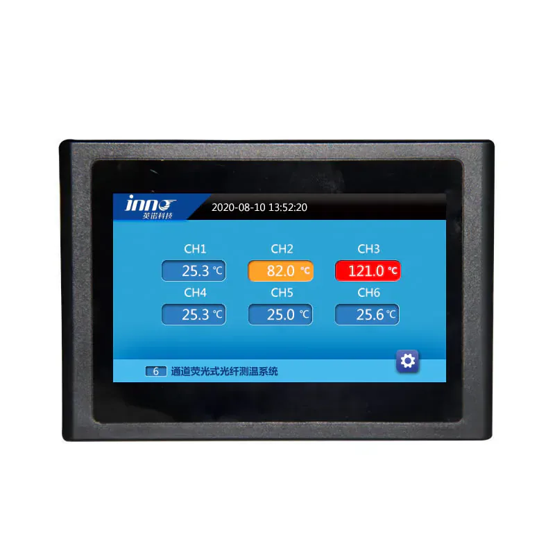
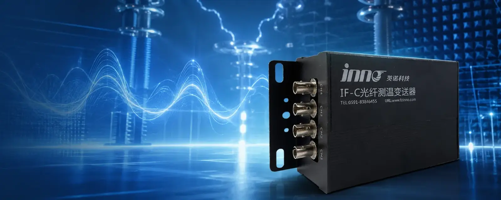
Fluorescent fiber optic temperature measurement for high-voltage, strong-EMI and RF environments where conventional electrical sensors may be unreliable. This optical path supports EMI/RFI immune temperature measurement and electrically isolated temperature measurement for power equipment testing, laboratories, industrial systems and other demanding applications.

ElectricalIsolation
EMIImmunity
No Metal atSensing Tip
Reliable inStrong Fields

THE CHALLENGE

Why Conventional Electrical Sensors Struggle in EMI Environments

High-voltage systems, power electronics, RF equipment and electromagnetic test setups generate intense electrical noise and potential. Conventional sensors with metal conductors can pick up noise, create ground loops and even pose safety risks.

FactorConventional Electrical SensorsFiber Optic Measurement
Electrical Isolation× Requires electrical connection (ground loops, leakage risk)✓ Fully electrically isolated (intrinsically safe)
EMI / RF Susceptibility× Susceptible to EMI, RF, EFT and surge✓ Immune to EMI, RF, EFT and surge
Safety in High Voltage× Metal conductors can float to high potential✓ Non-conductive sensing; no spark-over path
Signal Stability× Noise and ground loops affect accuracy✓ Stable, drift-free measurements in harsh EMI
Installation Suitability× Requires shielding, grounding and complex routing✓ Lightweight dielectric fiber; easy to route

Targeted Solutions for Electrically Demanding Environments

Precision temperature monitoring where electrical noise, high voltage and safety concerns make conventional sensors unreliable.

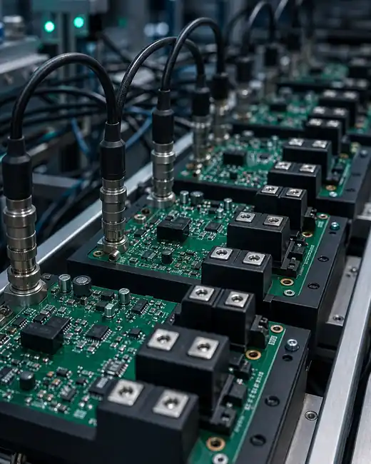
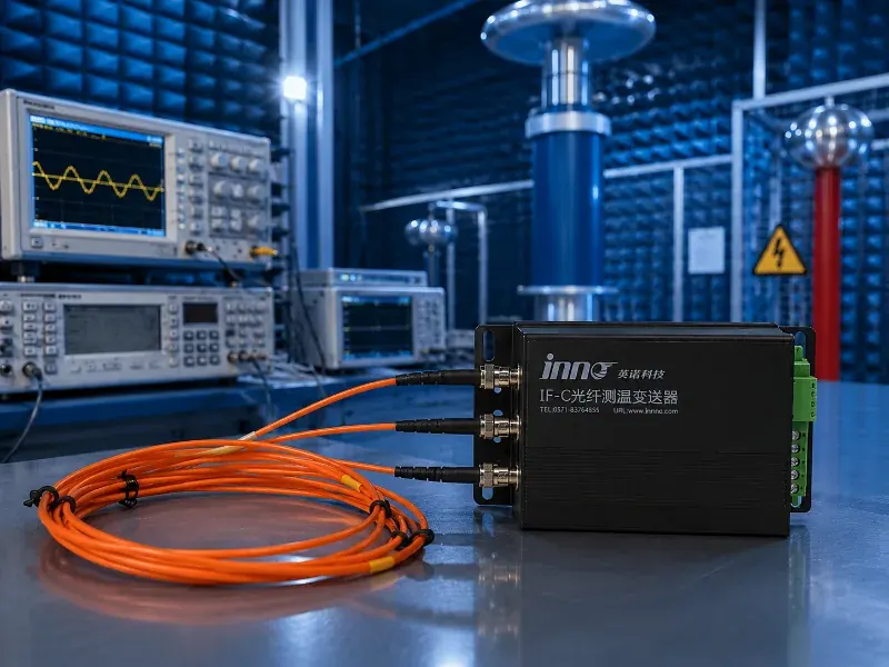
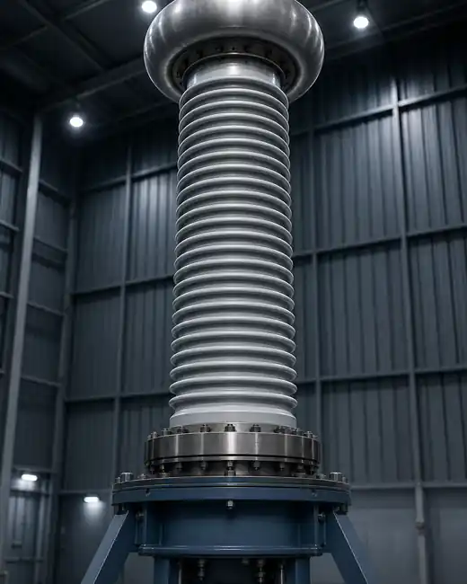
High-voltage test laboratory using interference-resistant temperature measurement

Stable Temperature Measurement in
High-Voltage Test & EMI-Rich Environments

INNO fiber optic solutions deliver accurate, drift-free temperature data in environments with strong electromagnetic interference and high electrical potential. The passive optical sensing path keeps conductive wiring away from the measurement point, supporting dependable monitoring without compromising operator or equipment safety.

  • Electrical isolation at the sensing point helps protect personnel and connected test equipment

  • Immunity to strong EMI and RF fields supports stable, interference-resistant temperature data

  • Direct point measurement captures temperature at critical components inside conductive setups

  • Safer monitoring where conventional electrical sensors are unsuitable, unreliable or restricted

Discuss Your Application →

Application-Specific Configuration for
Lab, MRI, Microwave and Industrial Systems

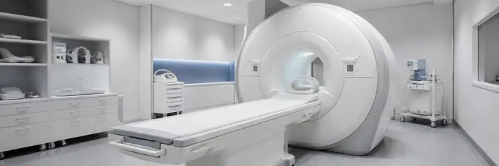
We design EMI-immune temperature measurement solutions around your system architecture, installation space, sensing locations and monitoring workflow. Each configuration can combine suitable probes, optical routing, instruments and data interfaces for laboratory, medical, microwave and industrial equipment.

  • Probe selection matched to the measurement point, temperature range and operating environment

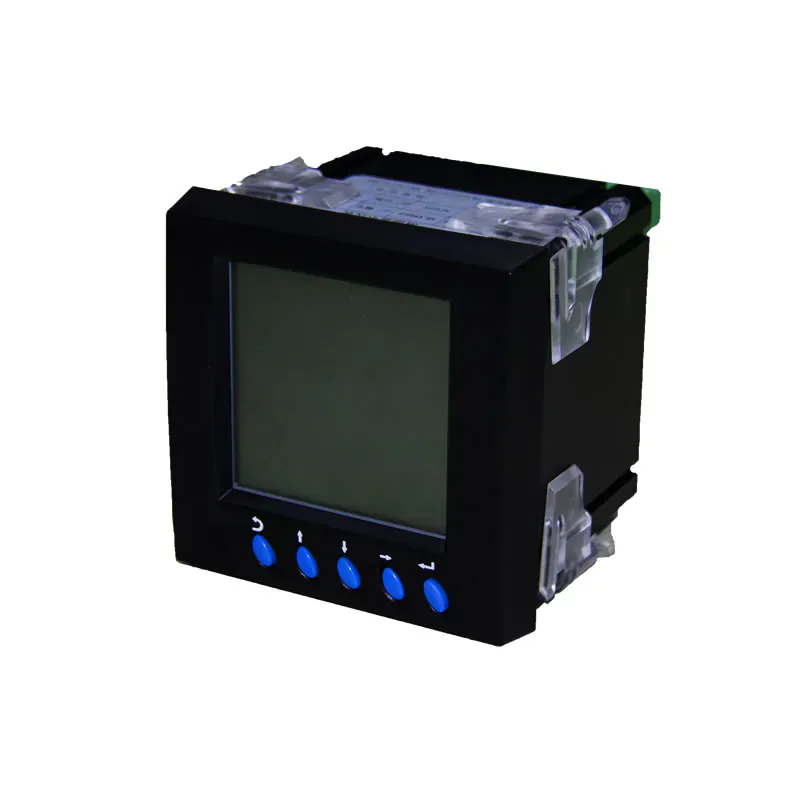
  • Compatible transmitter and display options for laboratory, rack, panel or field installation

  • Integration with PLC, DAQ or SCADA platforms for centralized monitoring and data review

  • Mechanical layout, enclosure and installation configuration adapted to the equipment structure
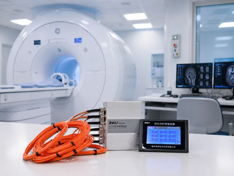
MRI, microwave and industrial equipment for application-specific temperature monitoring

KEY MEASUREMENT CHALLENGES

Temperature Measurement Challenges

Electrical interference, high voltage and complex installations can make conventional temperature measurement difficult.

Strong EMI & RF Fields

Electrical signals can be affected by electromagnetic interference.

High Electrical Potential

Electrical sensors may require additional isolation in high-voltage environments.

Long Cable Routing

Conductive cables can pick up interference over long distances.

Electrical Noise

Noise can affect stable and reliable temperature measurements.

Why the Method Remains Immune in Strong Fields

No Conductive Path

No metal at the sensing point eliminates direct conduction of EMI or surge energy.

No Ground Loop

Optical isolation breaks ground loops and common-mode voltage paths.

Immune to RF Coupling

Light in fiber is unaffected by electric, magnetic or RF fields.

High-Voltage Safe

Dielectric construction withstands high common-mode voltages.

Stable Long-Distance Routing

Fiber enables long runs in harsh routes without signal degradation.

Reliable Repeatability

High repeatability with minimal drift under demanding conditions.

Typical Deployment Models

Bench Validation

Bench Validation

Temperature verification during component and high-voltage laboratory tests.

Rack-Mounted Test System

Rack-Mounted Test System

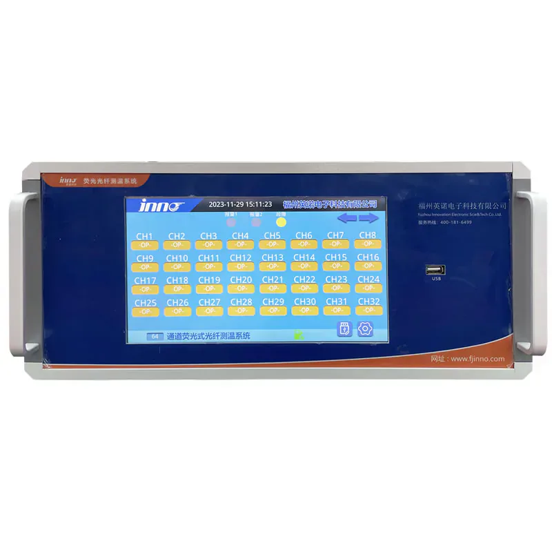
Centralized multi-channel acquisition for repeatable test programs.

OEM Equipment Integration

OEM Equipment Integration

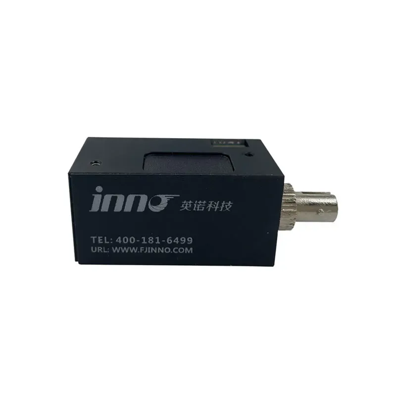
Compact sensing modules integrated into customer equipment and controls.

Permanent Industrial Monitoring

Permanent Industrial Monitoring

Continuous isolated measurement around energized production assets.

PROJECT PLANNING

How to Specify a High-Voltage & EMI-Immune Project

01

Measurement Location

Where is temperature measured?

02

Voltage Level

Nominal operating voltage and test voltage?

03

EMI / RF Source

Type, frequency range and severity?

04

Expected Temperature Range

Minimum / maximum temperature and operating conditions?

05

Cable Routing Distance

Sensor-to-instrument distance?

06

Installation Space

Rack, panel, enclosure and access constraints?

07

Required Response Time

How fast should the system respond?

08

Output / Integration Needs

Interfaces, protocols and system integration?

Engineering Review Checklist

01Measurement points and critical components identified

02Voltage class and isolation requirements confirmed

03EMI / RF environment characterized

04Temperature range and accuracy requirements defined

05Fiber routing path and distance verified

06Mounting, enclosure and environmental constraints checked

07Response time and data logging requirements confirmed

08System outputs and integration interfaces specified

✓ Complete this checklist for a faster engineering review and accurate system design.

TECHNOLOGY COMPARISON

When Fiber Optic Measurement Is the Better Choice

CriteriaThermocouplesRTDsFiber Optic Sensors
Electrical IsolationExtra isolationExtra isolationDielectric
EMI / RF ImmunityShielding neededShielding neededImmune
High-Voltage UseLimitedLimitedWell suited
Signal CableConductiveConductiveOptical
Strong Fields / RFLimitedLimitedWell suited

PROJECT IMPACT

Typical Project Outcomes

30–60%

Cleaner Temperature Data

Eliminate EMI noise and measurement errors for more accurate results.

100%

Improved Electrical Safety

Galvanic isolation removes ground loops and high-voltage shock risks.

40–70%

Easier Qualification Testing

Fewer re-tests due to EMI issues and unreliable measurements.

Long-Term

Reliable Monitoring

Stable performance in harsh, high-voltage, and EMI-rich environments.

SOLUTION STRATEGY

Where This Solution Fits in a Complete Measurement Strategy

Combine EMI-immune measurement with other INNO solutions for a complete temperature monitoring system.

APPLICATION REVIEW

Discuss Your High-Voltage Equipment Application

Share the measurement location, electrical environment, sensing points and required outputs so our engineers can recommend a suitable fiber optic monitoring configuration.

Contact Engineering

FAQ

High-Voltage & EMI-Immune Measurement FAQs

Why are fiber optic sensors immune to EMI?

The sensing path is dielectric and carries light rather than an electrical measurement signal, so electromagnetic and radio-frequency fields do not induce measurement noise in the probe.

Can they be used near high-voltage conductors?

Yes. The passive, non-conductive probe can be reviewed for selected measurement points near energized equipment where electrical isolation is required.

What temperature range is available?

The standard available temperature range is -40°C to +260°C. For applications requiring a wider range, contact INNO to review a custom probe and system configuration.

Can this solution be used for transformer winding temperature measurement?

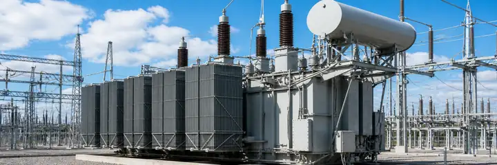
Yes. A passive, non-conductive fluorescence probe can measure a selected winding hot spot directly while the optical sensing path remains resistant to electromagnetic interference and electrically isolated from the monitored point.

Can data be sent to PLC or SCADA?

Yes. Reviewed monitoring hosts can provide industrial communication and alarm outputs for PLC or SCADA integration.

Are the sensors suitable for RF and microwave systems?

Yes. Their passive optical sensing path is suitable for RF, microwave and strong-EMI environments when probe placement and materials are reviewed.

Where can this solution be applied?

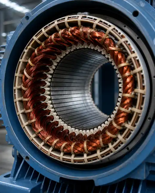
It can be used for transformer windings, switchgear and busbar connections, motors and generators, high-voltage test equipment, power electronics, MRI and RF systems, and industrial microwave or induction-heating equipment.

What measurement accuracy is available?

Depending on the selected probe and monitoring instrument, the available measurement accuracy is typically ±0.5°C to ±1.0°C.

Review a High-Voltage Measurement Configuration

Share the equipment, measurement points and EMI conditions so engineering can specify a suitable monitoring path.

Contact Engineering →Request a Configuration →
Contact Engineering

Tell us about your application, or contact us directly by Email: info@innofj.com