
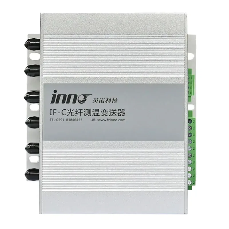
IF-C Multi-Channel Fiber Optic Temperature Transmitter
A configurable optical signal-processing host for connected fluorescence fiber optic temperature probes.
OPTICAL TEMPERATURE SIGNAL PROCESSING
IF-C Multi-Channel Fiber Optic Temperature Transmitter
This device is the transmitter, demodulator and monitoring host within a fluorescence fiber optic temperature measurement system. It receives optical signals from separately connected probes and converts them into real-time temperature values.
Fiber optic probes are required and selected separately. Channel count, compatible probe configuration, alarm outputs and communication options are chosen around the equipment and plant interface requirements.
- Configurable from 1 to 64 temperature channels
- Designed for use with electrically isolated fluorescence probes
- RS485 / Modbus communication with optional analog outputs
- Dual relay alarms for local protection and control logic
Product Overview
The multi-channel fiber optic temperature transmitter is the central signal-processing host for separate fluorescence probes. It converts the optical response from approved sensing channels into temperature data and can be configured around the project’s display, alarm, relay and communication requirements.
It is not a sensing probe and it does not decide where the measurement point should be. Select the probe construction, channel count and output plan from the actual asset before final configuration. The standard configuration supports 1–64 configurable channels, RS485/Modbus communication, relay outputs and optional analog outputs.
Choose the separate nine-channel host when the approved schedule specifically fits nine points. Choose this configurable transmitter family when the channel count, output mix or future expansion needs broader planning.
CHANNEL ARCHITECTURE
How Multi-Channel Acquisition Reduces Cabinet Complexity
One central host can consolidate several application-specific point measurements when the channel plan and probe locations are defined together.
- Match the required number of points to the selected channel configuration.
- Keep probe construction specific to each measurement location.
- Centralize approved temperature outputs at the panel level.
PLANT INTERFACE
Planning PLC and SCADA Outputs
Communication and outputs should be determined by the monitoring architecture, not assumed from the transmitter name.
- Review RS485 or Modbus requirements.
- Define relay and optional analog-output use.
- Confirm the data and alarm interface with the control system team.
MEASUREMENT WORKFLOW
How the Multi-Channel Fiber Optic Temperature Transmitter Works
The transmitter is the signal-processing stage between individual point probes and the plant monitoring system. It is not the probe itself and it is not distributed temperature sensing.
Fiber Optic Probe
Measures temperature at one defined point.
Optical Signal
Carries the fluorescence response to the host.
Multi-Channel Transmitter
Demodulates each connected probe and calculates temperature.
Industrial Output
Provides configured RS485, analog or relay outputs.
PLC / SCADA
Receives centralized temperature data for monitoring and control.
REQUIRED SENSING ELEMENTS
Compatible Fiber Optic Temperature Sensors
The transmitter receives and processes optical signals; the actual temperature measurement takes place at a separately connected fluorescence fiber optic point probe.
View the compatible fiber optic temperature probeStandard point probes
General industrial hot-spot measurement with a separately selected fiber lead.
Application-packaged probes
Probe sheaths, diameters and installation structures selected for the monitored asset.
Custom fiber lengths
Optical lead length configured around routing distance and cabinet position.
HOST CAPABILITIES
Key Features
Direct Point Measurement
Fluorescence-based optical sensing measures temperature at the installed probe tip.
Configurable Channels
Select 1–64 measurement channels to match asset size and monitoring scope.
Probe Compatibility
Pair the host with non-conductive fluorescence probes selected for the installation.
Fast Response
A measurement cycle below one second supports timely alarm and control decisions.
Plant Integration
RS485 / Modbus and configurable analog outputs connect temperature data to control systems.
Application Configured
Probe length, channel count, output type and alarm logic can be reviewed for each project.
CONFIGURATION DATA
Technical Specifications
Select the channel count, compatible probe arrangement and output interface for the application.
Specifications and available options may change with the selected enclosure, channel quantity and project requirements.
Key Parameters to Confirm Before Ordering
INDUSTRIAL DATA CONNECTION
PLC & SCADA Integration
Connected probes send optical signals to the transmitter. The transmitter converts each channel into temperature data, then sends the configured digital, analog or alarm output to the plant control or monitoring layer.
Interfaces and output quantities depend on the ordered configuration and should be confirmed against the PLC or SCADA I/O plan.
RS485 / Modbus
Centralized digital temperature data for a PLC, gateway or supervisory monitoring network.
4–20 mA or 0–20 mA
Optional analog output for control systems that require individual current-loop signals.
Relay alarms
Configured dry-contact outputs for local over-temperature alarm or protection logic.
WHERE MULTI-POINT ACQUISITION HELPS
Typical Multi-Point Temperature Monitoring Applications
Transformer Winding Hot Spots
Centralize temperature from multiple winding or core measurement points in one host.
Switchgear and Busbars
Acquire several contacts, busbar joints or cable termination temperatures without multiple standalone devices.
Generators and Motors
Monitor multiple winding, stator or high-potential measurement locations through one communication interface.
High-Voltage Equipment
Bring isolated point measurements from several energized locations into the plant monitoring system.
Industrial and Laboratory Tests
Record synchronized temperature data from multiple electrically isolated test points.
PRODUCT SELECTION
How to Choose the Right Fiber Optic Temperature Device
Choose the equipment role according to the number of points, operator interface and level of system integration—not only by the channel count.
COMPLETE THE MEASUREMENT PATH
Related Products
Combine the monitoring unit with the appropriate optical probes, transformer package or acquisition platform for the installation.
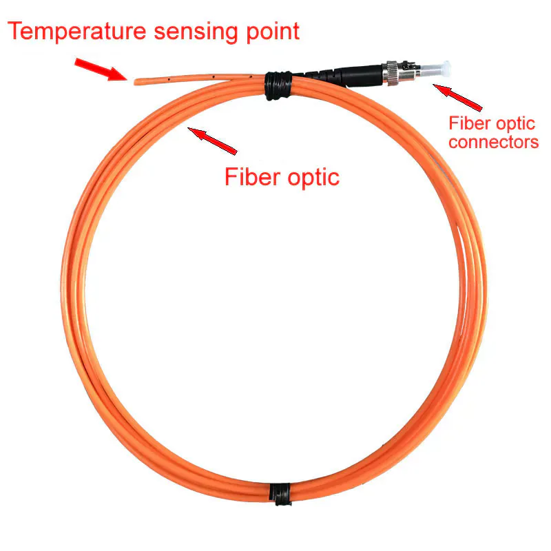
Standard Fluorescent Fiber Optic Temperature Probe
Non-conductive point probe for electrically demanding measurement environments.
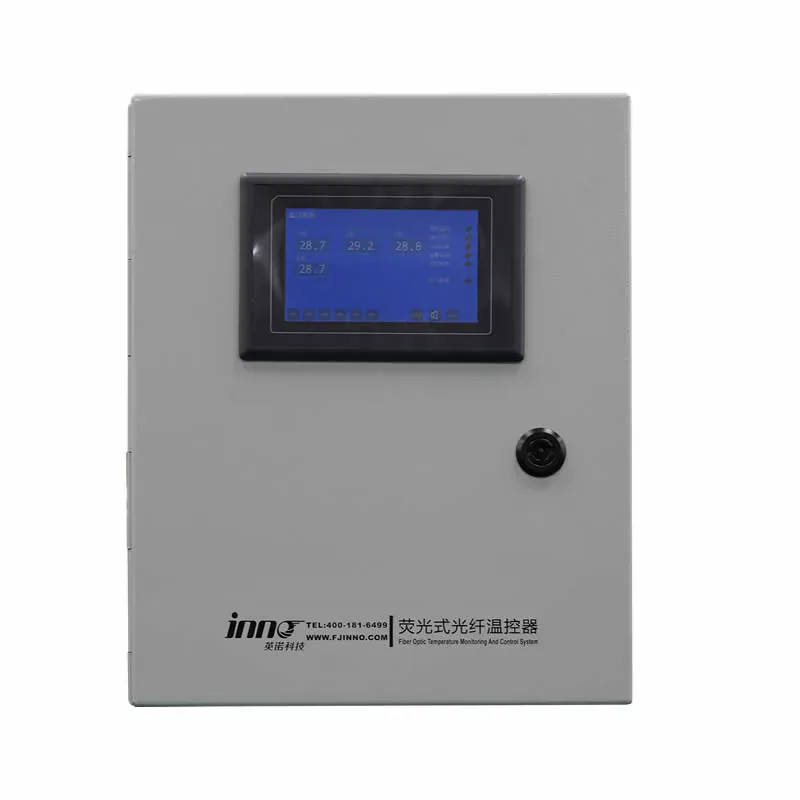
Dry-Type Transformer Monitoring System
Configured probes and monitoring hardware for dry-type transformer winding points.
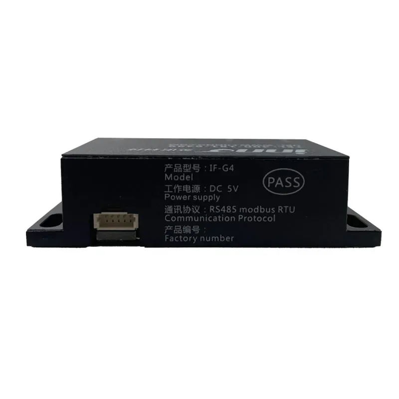
IF-G4 Four-Channel OEM Temperature Module
Compact acquisition hardware for equipment and monitoring-system integration.
BUYER QUESTIONS
Frequently Asked Questions
How many fiber optic temperature sensors can one transmitter support?
The product supports configurations from 1 to 64 channels. One measurement channel normally corresponds to one connected point temperature probe.
Can the transmitter work with fluorescent fiber optic temperature probes?
Yes. It is designed to receive signals from compatible fluorescence fiber optic point probes. Probe construction and fiber length must be selected for the application.
Does the transmitter support RS485 and Modbus communication?
RS485 and Modbus communication are available in the standard product configuration. Confirm the required protocol and interface when ordering.
Can temperature data be sent to a PLC or SCADA system?
Yes. A configured RS485 interface can send centralized temperature data to industrial control or supervisory systems. Optional analog outputs can also be specified when required.
How do I choose the required number of channels?
Count the individual temperature measurement points, then allow for the required spare capacity and cabinet arrangement. INNO can review the measurement-point list before configuration.
Can the channel count and output interface be customized?
Channel quantity, analog outputs, communication and enclosure arrangement are selected according to the available product configuration and project requirements.
What is the difference between a transmitter and a temperature monitor?
A transmitter focuses on signal demodulation, temperature conversion and industrial output. A monitor may additionally emphasize local display, operator controls, data storage or alarm visualization.
Is this a distributed fiber optic temperature sensing system?
No. This product is for point-based fluorescence fiber optic temperature sensing with individual probes. It is different from distributed temperature sensing, which measures continuously along an optical fiber.
CONFIGURATION SUPPORT
Need Help Selecting the Right Configuration?
Tell our engineering team about the asset, temperature range, number of measurement points, fiber routing and required plant communication. We will review the information and recommend a suitable configuration.
- Application and channel review
- Probe and fiber configuration support
- Output and communication selection
Discuss Your Temperature Monitoring Application
Share your requirements with an INNO application engineer.