
Polyimide Transformer Winding Fiber Optic Temperature Probe
A slim, passive point probe for reviewed transformer winding and internal hot-spot installations.
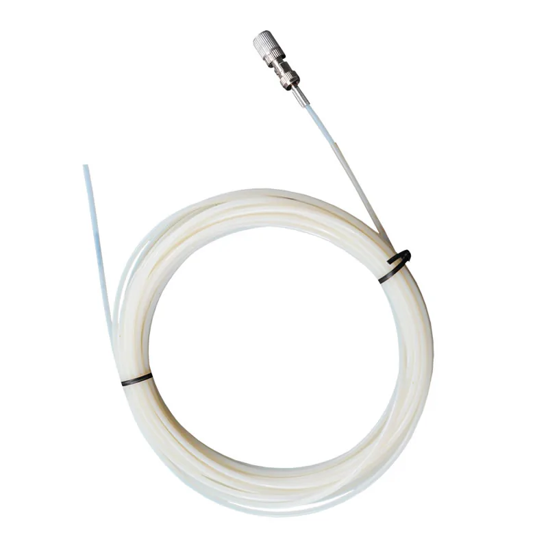
POLYIMIDE-PROTECTED WINDING PROBE
Protect the Optical Path With Polyimide Construction
This probe uses a polyimide protective construction for selected transformer winding and internal temperature measurement points.
The probe does not provide a temperature output by itself. One compatible fluorescence channel is required for each point, and the complete installation must be coordinated with the transformer insulation and assembly design.
- Polyimide protective construction
- -40 °C to +260 °C range
- 2.5 mm sensing tip
- Passive, electrically isolated probe
Product Overview
The polyimide-enhanced transformer winding temperature probe is a passive fluorescence probe for a selected internal winding point. Its polyimide protective construction and 2.5 mm sensing-tip diameter support projects where a compact probe geometry is part of the installation review.
A probe provides the measurement point, not the complete monitoring function. Connect it to a compatible fluorescence instrument when the project also requires temperature display, alarming, logging or plant communication.
WINDING INTEGRATION
Where a Slim Winding Probe Fits
A compact sensing tip can be valuable where the winding build and insulation structure leave limited room for a measurement assembly.
- Direct point measurement at a selected internal location.
- Passive optical sensing path at the temperature point.
- Project review required for final probe placement and route.
INSTALLATION COORDINATION
Coordinating Probe Placement With Transformer Insulation
The probe should be selected as part of the internal construction plan, not after the winding point is inaccessible.
- Review the target point with the transformer designer.
- Confirm fiber routing and protection through the build.
- Select a compatible channel count for all planned points.
SHARED MEASUREMENT PRINCIPLE
Passive Point Sensing With a Compatible Instrument
The fluorescent sensing tip measures one selected point. A compatible instrument supplies the optical excitation, processes the returned signal and provides the temperature output. See the standard fluorescence probe for the full measurement principle.
PRODUCT CONSTRUCTION
Slim Polyimide Winding Probe Construction
The compact protective construction is selected around available winding space, insulation coordination and the planned optical route.
Polyimide protective construction
The optical route uses the product’s polyimide protection for the selected internal installation.
Compact sensing tip
The fluorescent tip is positioned at the defined winding or internal temperature point.
Optical lead to host
The fiber route ends at a compatible fluorescence instrument selected for the project.
PRODUCT SELECTION
When to Choose the Polyimide-Enhanced Probe
Choose this configuration for transformer projects that need a slim protective optical construction and direct point measurement.
- Transformer winding hot spots
- Internal transformer temperature points
- Slim optical routing paths
- Embedded point measurement planning
- Application-specific insulation review
APPLICATION-SPECIFIC ADVANTAGES
Key Probe Features
Polyimide Protection
A polyimide construction protects the application-specific optical route.
Direct Internal Measurement
The sensing tip is placed at the actual temperature point.
Slim Geometry
The standard configuration supports a 2.5 mm sensing tip and 3 mm cable.
Passive Optical Path
The sensing point contains no powered electronics.
EMI Immunity
Temperature information returns optically through the fiber.
Transformer-Specific Review
Routing, fixing, material compatibility and connector position are confirmed for the project.
TECHNICAL SPECIFICATIONS
Technical Specifications
Choose the final probe construction and compatible instrument for the application.
Parameters to Confirm Before Ordering
INSTALLATION PLANNING
Integrate the Probe Into the Winding Design
The sensing tip must contact the actual temperature point while the optical route is protected through the equipment.
Target Point
Optical Route
Compatible Instrument
- Define the true winding hot spot or internal target point.
- Confirm the polyimide route and fixing method before assembly.
- Maintain reviewed bends and protect the optical connector end.
- Match probe quantity to compatible instrument channel count.
PRODUCT TO INDUSTRY
Typical Applications
Open the related industry or solution page for application-specific measurement and installation guidance.
RELATED PRODUCTS
Compatible Products for This Application
These products have different roles in the measurement path and are selected according to the installation.
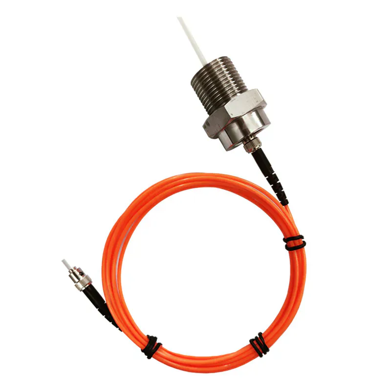
Armored Transformer Winding Probe
Provides a different construction where stronger mechanical route protection is required.
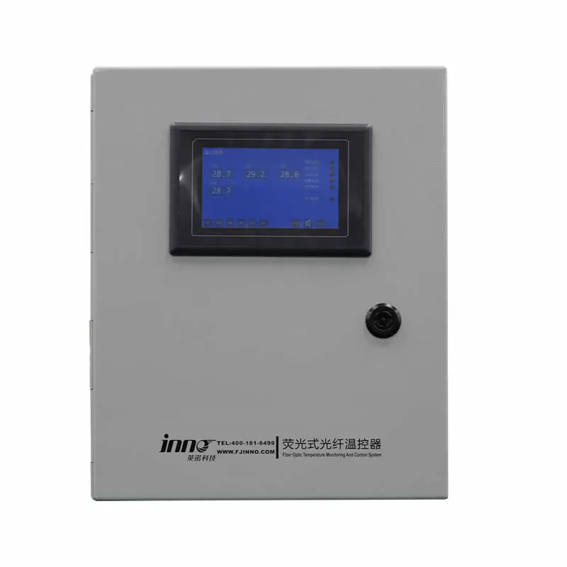
Dry-Type Transformer Monitoring System
Combines selected probes and monitoring hardware for dry-type winding points.
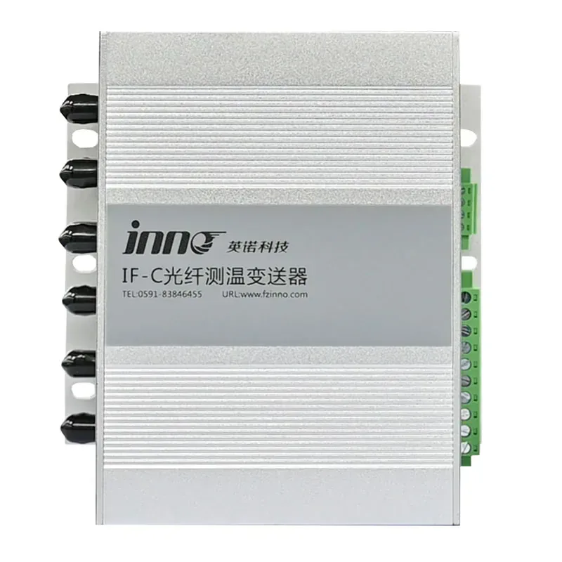
Multi-Channel Fiber Optic Temperature Transmitter
Centralizes data from multiple selected winding points.
BUYER QUESTIONS
Frequently Asked Questions
Why use polyimide protection?
It provides a slim protective construction for the optical route in application-specific transformer installations.
Is this a complete transformer monitoring system?
No. It is a passive probe and requires a compatible instrument, optical connections and project-specific installation.
How many locations does one probe measure?
One probe measures at one fluorescent sensing tip.
What range is for this configuration?
The standard configuration supports -40 °C to +260 °C. Final performance must be confirmed for the selected construction.
Can the dimensions be customized?
Probe geometry and routing requirements can be reviewed, but final availability must be confirmed for the project.
What should the transformer manufacturer provide?
Provide winding drawings, target points, insulation environment, route constraints, temperature range and required probe quantity.
PROBE SELECTION SUPPORT
Configure a Polyimide Winding Probe
Send the transformer winding drawing, target points, temperature range, internal route and required channel count.
- Measurement location
- Required temperature range
- Fiber route and length
Need Help Selecting the Correct Probe Construction?
Share the measurement point, environment and installation constraints with INNO.