
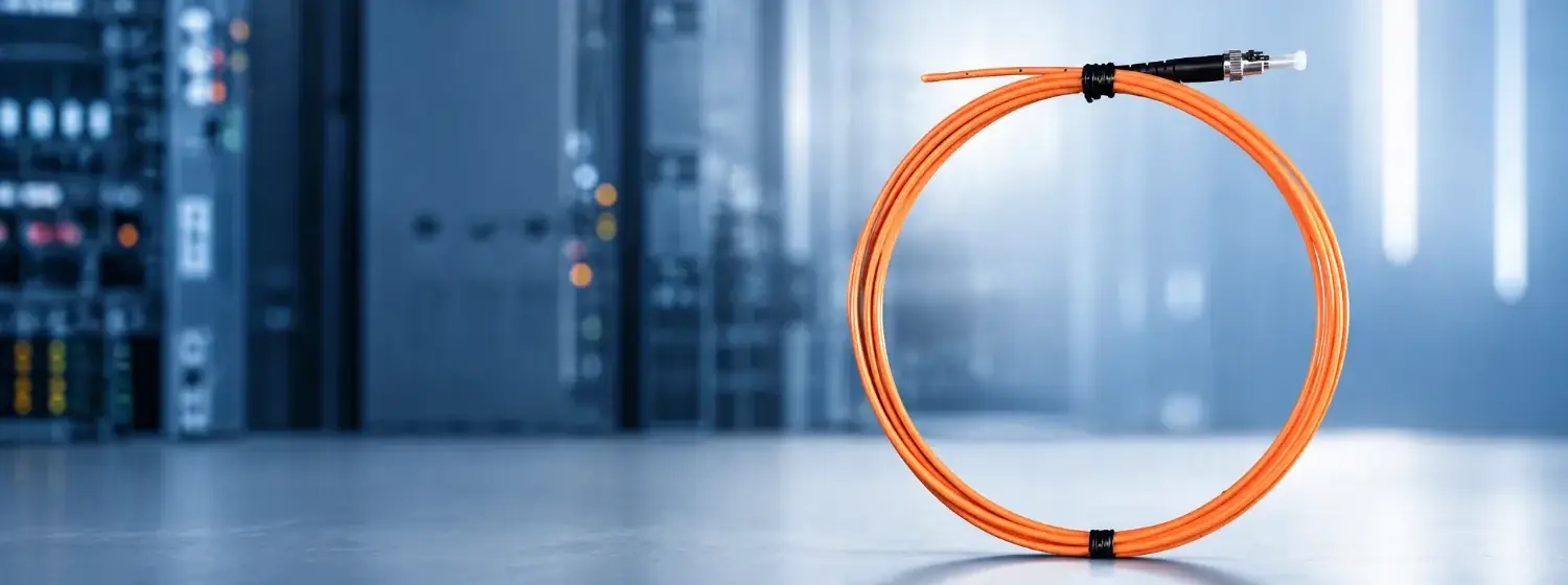
TECHNOLOGY
Fluorescent Fiber Optic
Temperature Sensing Technology
INNO’s fluorescent fiber optic temperature sensing technology provides real-time point temperature data in electrically harsh environments. The sensing path is non-conductive and electrically isolated for reviewed applications where conventional sensors are unsuitable.
What Is Fiber Optic Temperature Measurement?
Fiber optic temperature measurement uses the temperature-dependent decay time of fluorescence to measure temperature at a specific location. In this fluorescent approach, the probe and optical fiber carry light rather than an electrical measurement signal, supporting direct point readings in high-voltage, high-noise and electrically demanding environments.
FLUORESCENCE DECAY METHOD
How Fluorescence Decay Temperature Measurement Works
Four linked stages turn an optical response into a direct point temperature reading.
Optical Excitation
Excitation light travels through the fiber to fluorescent material at the probe tip.
→Fluorescence Emission
The sensing material emits an optical response at the defined measurement point.
→Fluorescence Decay
The returned fluorescence decreases over time as temperature changes.
→Temperature Calculation
A compatible instrument evaluates the response and calculates temperature.
SYSTEM ARCHITECTURE
Core Components of a Fiber Optic Temperature Measurement System
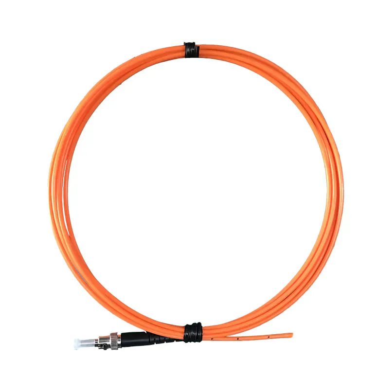
Fiber Optic Temperature Probe
Fluorescent sensing material at the selected measurement point.
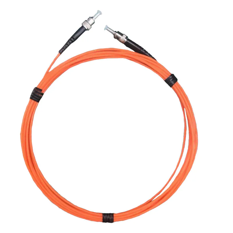
Optical Fiber & Extension Cable
Excitation and return light between probe and instrument.
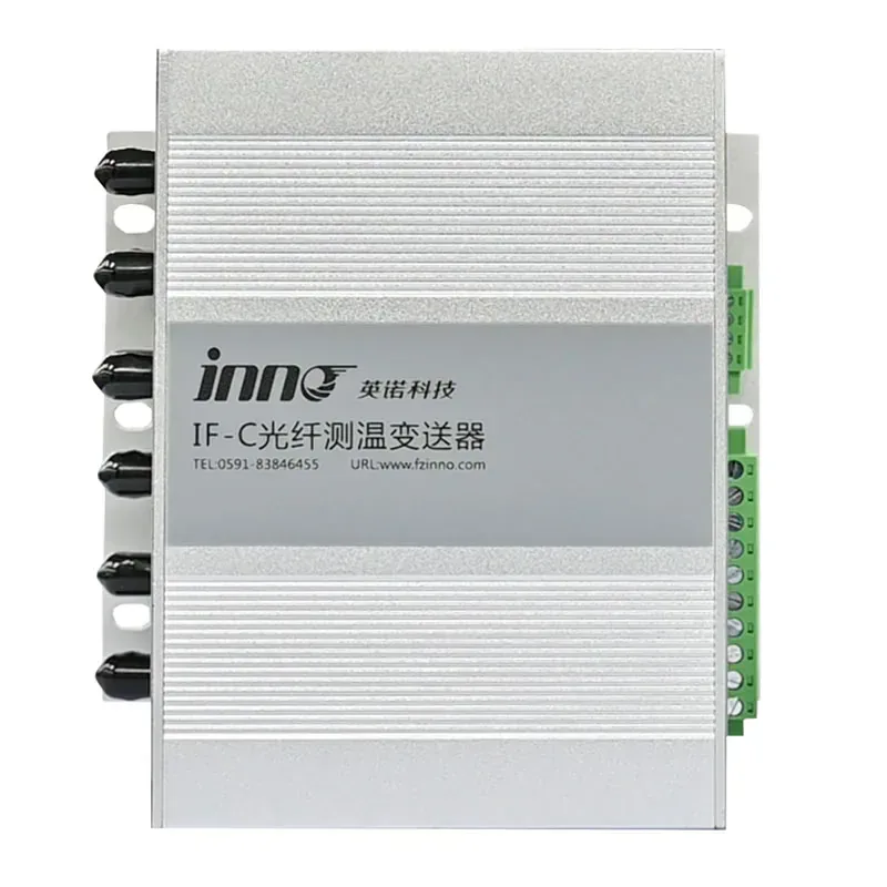
Monitoring Host
Optical-response evaluation and channel temperature output.
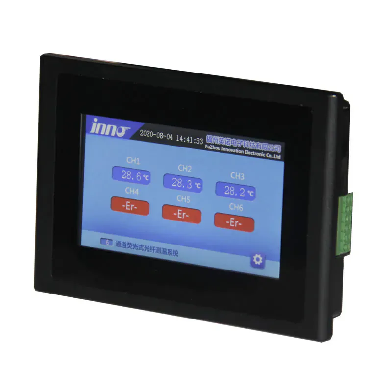
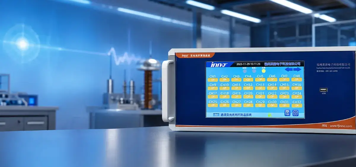
Fiber Optic Temperature LCD Display Instrument
A local LCD display instrument for reviewed fiber optic temperature measurement arrangements and panel integration projects.
BUILT FOR ELECTRICALLY DEMANDING ENVIRONMENTS
Why Fiber Optic Temperature Measurement Resists EMI and RFI
Electrical Isolation
No electrical measurement signal at the sensing point, supporting electrically isolated temperature measurement.
EMI Immunity
Optical transmission supports EMI/RFI immune temperature measurement without conductive sensor wiring at the point.
RF Compatibility
Non-metallic probes for reviewed RF-sensitive environments.
Direct Point Reading
Each probe measures one selected physical point.
Flexible Routing
Probe length and protection reviewed around the installation.
TECHNOLOGY COMPARISON
Fluorescent Fiber Optic Temperature Sensors vs RTD / PT100
Both are point temperature measurement technologies, but they differ significantly in signal transmission, electrical isolation, EMI immunity, and installation requirements.
| Consideration | Fluorescent Fiber Optic | RTD / PT100 |
|---|---|---|
| Measurement principle | Optical excitation and fluorescence decay | Resistance change of a metallic sensing element |
| Signal path | Optical fiber | Electrical wiring |
| Electrical isolation | Non-conductive optical sensing path | Conductive electrical connection |
| EMI / RF immunity | Optical sensing path is immune to electromagnetic interference | Electrical leads can be affected by electromagnetic interference |
| High-voltage environments | Well suited to measurements where electrical isolation is required | Requires appropriate insulation, wiring and installation design |
| Sensor connection | Probe connected to an optical transmitter or demodulator | Sensor connected to an RTD-compatible transmitter or readout |
| Typical selection | High-voltage, RF, microwave and strong electromagnetic-field environments | General industrial temperature measurement and conventional equipment |
ENGINEERING VALUE
Key Advantages of Fluorescent Fiber Optic Temperature Sensors
The technology is most useful when measurement architecture, electrical environment and installation are evaluated together.
Non-Conductive Sensing
No electrical sensor signal is introduced at the sensing point.
Galvanic Isolation
The measurement point is optically separated from electronics.
Field-Immune Signal
Temperature information travels optically.
Defined-Point Data
Every channel stays linked to a known location.
Scalable Channels
Single-point and multi-channel architectures.
Integration Outputs
Reviewed data can connect to plant controls.
APPLICATIONS
Where Fluorescent Fiber Optic Temperature Sensing Is Used
Direct point monitoring where isolation, field immunity or non-metallic sensing is important.

Transformer Monitoring
Windings, hot spots and selected internal points.
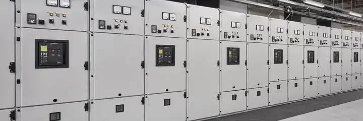
Switchgear & Busbars
Contacts, joints and cable terminations.

Motors & Generators
Windings, stators and rotating-equipment tests.
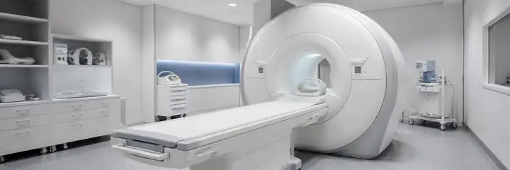
Medical & MRI
Reviewed non-metallic sensing around RF-sensitive equipment.

Industrial Microwave
Direct point monitoring for microwave heating.
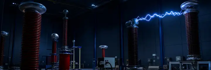
High-Voltage Testing
Electrically isolated measurement in test environments.
How to Choose a Fiber Optic Temperature Sensor
Selecting the right sensor and system depends on your measurement needs and operating environment. Use these key criteria to guide your decision.
1. Measurement Range
Choose a sensor that covers your expected temperature range with sufficient margin for accuracy and safety.
2. Probe Size & Form Factor
Select the appropriate probe diameter, length, and tip style based on installation space and target surface.
3. Sensing Point
Determine if you need surface contact or non-contact, and whether single-point or distributed sensing is required.
4. Environment
Consider temperature, humidity, chemicals, vibration, and whether the area is electrically noisy or hazardous.
5. Channel Count
Match the number of measurement points today with room to scale for future expansions.
6. Output & Integration
Ensure the system outputs and software integrate with your existing monitoring, control, and alerting infrastructure.
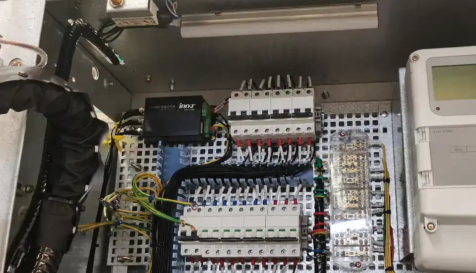
From Probe to Monitoring System
INNO’s fluorescent fiber optic temperature sensors connect to compatible signal-processing hosts, optical fiber and monitoring software to form a complete measurement system.
Fluorescent Fiber Optic Probes
Accurate, stable temperature measurement at the point of interest.
→Interrogation Host
Excites, measures, and processes signals from multiple channels.
→Monitoring Software
Real-time visualization, alerts, historical data, and system management.
INNO Fluorescent Fiber Optic Temperature Monitoring Technology
- Accurate and Stable: Temperature-dependent fluorescence provides high accuracy and long-term stability.
- Electrically Immune: No EMI, RFI, or ground loop issues—ideal for electrically harsh environments.
- Safe and Isolated: Complete electrical isolation enhances personnel and equipment safety.
- Industrial Construction: Specified for demanding industrial, power and critical-infrastructure applications.
- Application Support: Application engineers review selection and deployment requirements with your team.
RECOMMENDED NEXT STEPS
Build the Right Fiber Optic Temperature Measurement System
Fiber Optic Temperature Sensors
Point probes for electrical, RF and thermal environments.
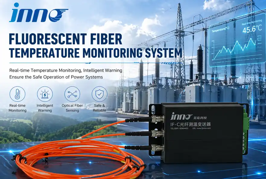
Monitoring Hosts & Transmitters
Compatible optical evaluation and temperature output.
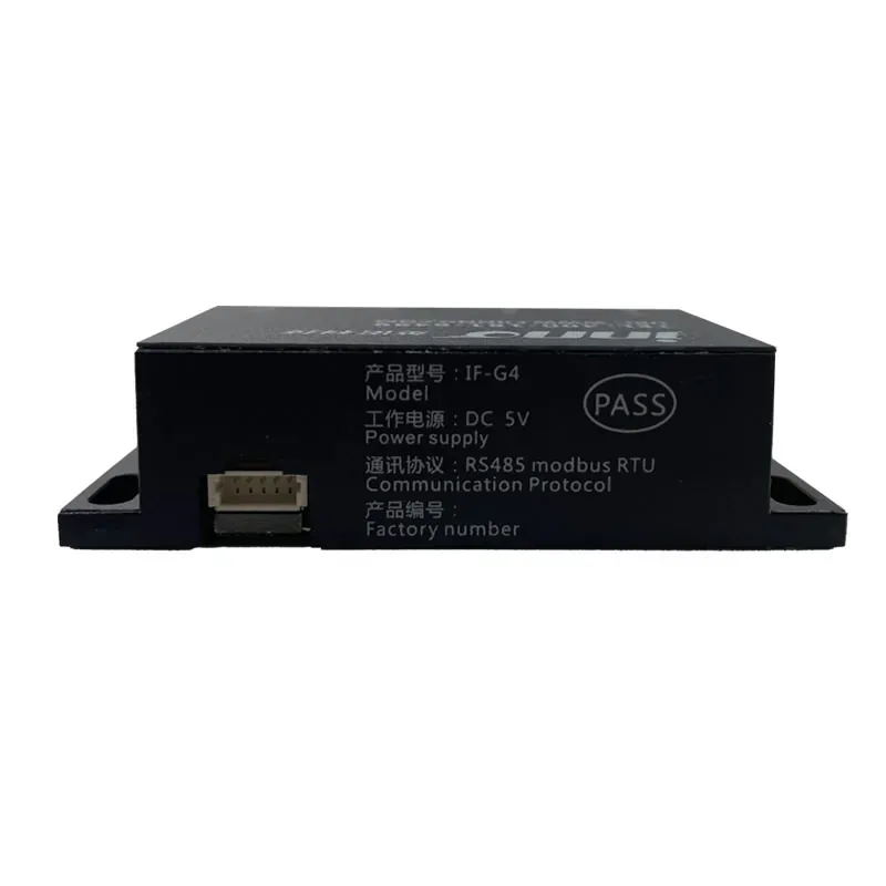
OEM Measurement Modules
Compact modules for reviewed equipment integration.
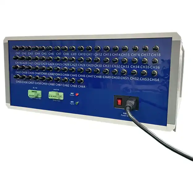
Multi-Point Systems
Independent probes organized around defined locations.
FAQ
Fluorescent Fiber Optic Temperature Sensing Questions
What is fluorescent fiber optic temperature sensing?
It is point temperature measurement using fluorescent material at a probe tip, optical excitation and temperature-dependent fluorescence decay.
Is it the same as DTS?
No. Fluorescent technology measures defined points with individual probes; DTS measures temperature distribution along a fiber route.
Can it work in high-voltage equipment?
It can be reviewed where electrical isolation, EMI immunity and a non-conductive sensing path are important.
Can it be used in MRI and RF environments?
Non-metallic optical probes can be configured for reviewed MRI and RF applications.
Can it be used in microwave heating?
It can support direct point measurement in reviewed microwave-heating and thermal-processing applications.
How many points can be monitored?
The number depends on the selected host and channel configuration; each probe represents an independent point.
Can the system connect to PLC or SCADA?
Reviewed configurations may use RS485, Modbus, configurable analog outputs or alarm outputs.
Can the probe configuration be customized?
Probe geometry, fiber length, protection and connection details can be reviewed around the installation.
ENGINEERING SUPPORT
Discuss Your Temperature Measurement Application
Share the measurement points, environment, temperature range, installation constraints, channel count and required outputs.
Contact Engineering →