
Armored Transformer Winding Fiber Optic Temperature Probe
Protected optical routing for direct point measurement inside oil-immersed transformer projects.
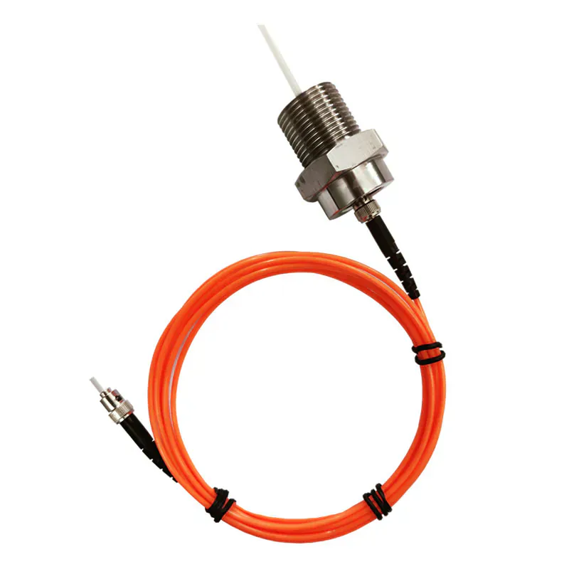
MECHANICALLY PROTECTED WINDING PROBE
Add Mechanical Protection to the Internal Optical Route
This probe adds an armored protective construction around the optical path for transformer winding and internal hot-spot measurement projects.
It remains a passive point sensor. Final material compatibility, bend routing, fixing method, insulation coordination and connection to a compatible instrument must be application-specific with the transformer design.
- Armored mechanical protection
- -40 °C to +260 °C range
- 3 mm armored cable diameter
- 100 kV probe configuration
Product Overview
The armored transformer winding fiber optic temperature probe is a passive point-measurement component for selected internal transformer locations. Its armored construction is intended to support a reviewed mechanical route during transformer assembly while the sensing tip is positioned at the temperature point of interest.
This product is not a complete transformer monitoring system. A compatible fluorescence transmitter or host is required to process the optical signal, display temperature and provide any alarm or communication functions.
TRANSFORMER ASSEMBLY
Mechanical Protection During Transformer Assembly
Internal installation needs both a meaningful sensing position and a route that can be considered within the transformer build process.
- Armored construction is intended for a protected optical route.
- Probe placement should be coordinated with winding and insulation design.
- Final routing and connector access require project review.
HOT-SPOT PLANNING
Routing a Probe to a Winding Hot Spot
The selected point should reflect the thermal question the monitoring project is trying to answer.
- Identify winding locations before final assembly.
- Avoid relying on an external surface measurement for an internal hot spot.
- Pair channel count with the planned number of points.
SHARED MEASUREMENT PRINCIPLE
Passive Point Sensing With a Compatible Instrument
The fluorescent sensing tip measures one selected point. A compatible instrument supplies the optical excitation, processes the returned signal and provides the temperature output. See the standard fluorescence probe for the full measurement principle.
PRODUCT CONSTRUCTION
Mechanically Protected Winding Probe Construction
This construction emphasizes protected internal routing during transformer assembly, while the fluorescent tip remains the defined measurement point.
Armored optical route
The protective construction supports a mechanically considered path through the transformer assembly.
Winding hot-spot tip
The sensing tip is placed at the selected internal winding or structural hot spot.
Instrument termination
The routed fiber connects to a compatible fluorescence channel outside the measurement point.
PRODUCT SELECTION
When to Choose an Armored Winding Probe
Choose this construction when internal routing needs more mechanical protection than a standard optical probe assembly.
- Oil-immersed transformer winding projects
- Internal routes exposed during assembly
- Defined winding or structural hot spots
- Projects requiring protected optical routing
- Application-specific installation review
APPLICATION-SPECIFIC ADVANTAGES
Key Probe Features
Armored Optical Route
Mechanical protection supports routing through application-specific transformer assembly paths.
Direct Winding Point
The sensing tip measures the selected internal point.
Transformer Application
Construction is intended for application-specific oil-immersed transformer projects.
Passive Sensing
No powered electronics are placed at the internal measurement point.
EMI Immunity
Optical transmission is unaffected by electromagnetic pickup.
Project Configuration
Tip position, protective route and connector details are confirmed for the transformer.
TECHNICAL SPECIFICATIONS
Technical Specifications
Choose the final probe construction and compatible instrument for the application.
Parameters to Confirm Before Ordering
INSTALLATION PLANNING
Coordinate the Probe With Transformer Assembly
The sensing tip must contact the actual temperature point while the optical route is protected through the equipment.
Target Point
Optical Route
Compatible Instrument
- Identify the target winding or internal hot spot before assembly.
- Review the armored route, fixing points and minimum bend radius.
- Confirm compatibility with transformer insulation and internal media.
- Terminate the optical route at the selected compatible instrument.
PRODUCT TO INDUSTRY
Typical Applications
Open the related industry or solution page for application-specific measurement and installation guidance.
RELATED PRODUCTS
Compatible Products for This Application
These products have different roles in the measurement path and are selected according to the installation.
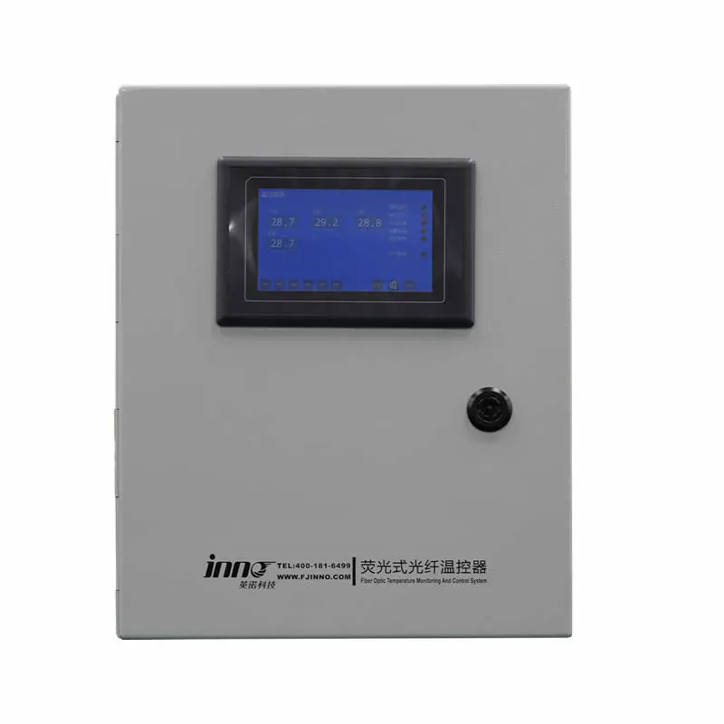
Dry-Type Transformer Monitoring System
Coordinates probes, monitoring hardware and outputs for a dry-type transformer.
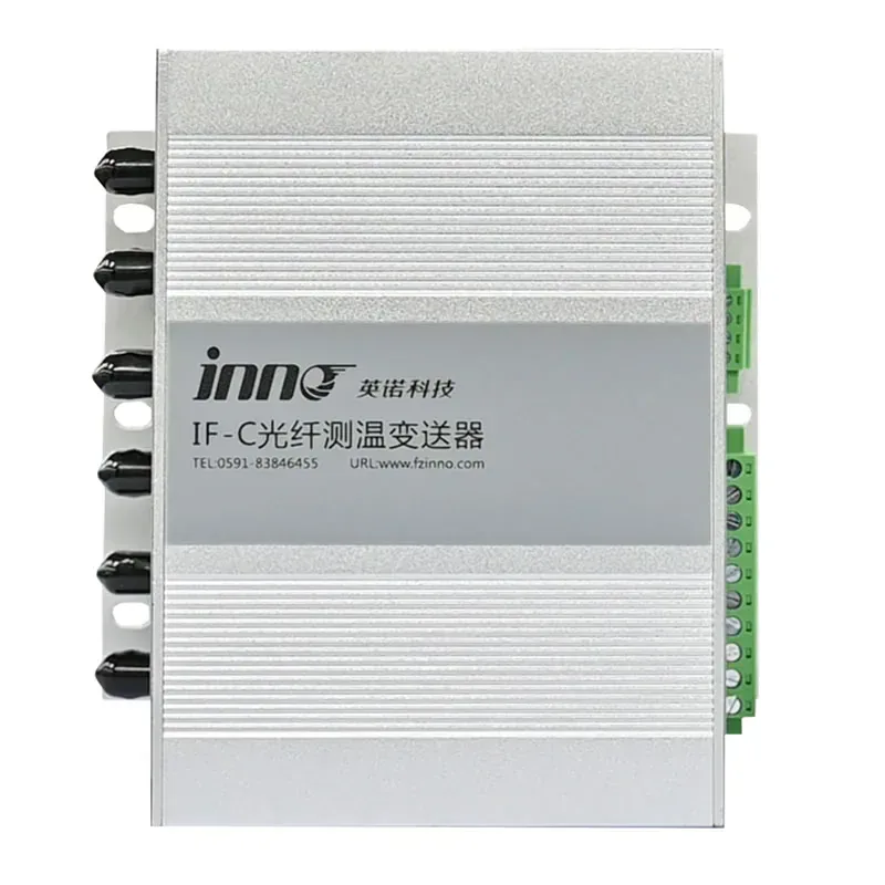
Multi-Channel Fiber Optic Temperature Transmitter
Processes several separately routed winding probes in one host.
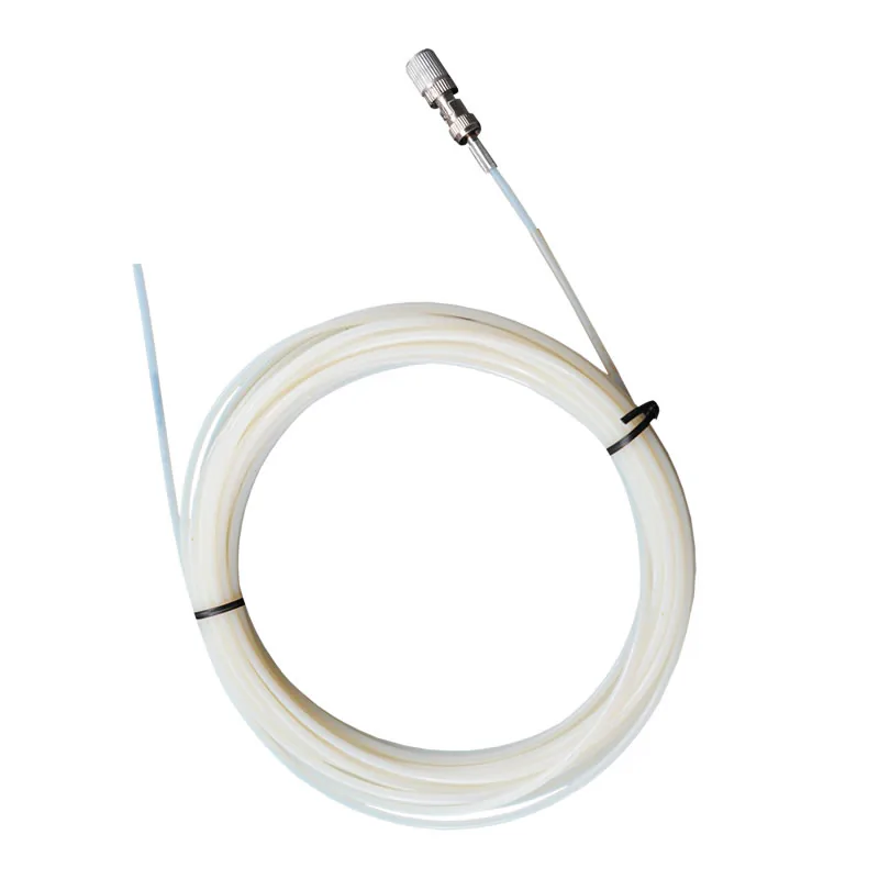
Polyimide Transformer Winding Probe
A slimmer construction for a different internal installation approach.
BUYER QUESTIONS
Frequently Asked Questions
What does the armored construction protect?
It provides added mechanical protection around the optical route; it does not replace the transformer insulation design.
Does the probe include the monitoring host?
No. The passive probe connects to a separately selected fluorescence transmitter or monitoring host.
Where is the sensing point?
Temperature is measured at the fluorescent sensing tip placed at the selected winding or internal hot spot.
Can it be installed after the transformer is assembled?
Installation access depends on the transformer design. Probe routing should normally be coordinated with the equipment manufacturer and assembly plan.
What information is needed for selection?
Provide the transformer type, measurement-point drawing, temperature range, internal route, bend constraints, probe quantity and instrument requirement.
Is it a continuous fiber temperature sensor?
No. It measures one defined point per probe.
PROBE SELECTION SUPPORT
Review an Armored Transformer Probe Configuration
Share the winding layout, internal route, media, temperature range, measurement-point quantity and compatible host requirement.
- Measurement location
- Required temperature range
- Fiber route and length
Need Help Selecting the Correct Probe Construction?
Share the measurement point, environment and installation constraints with INNO.