
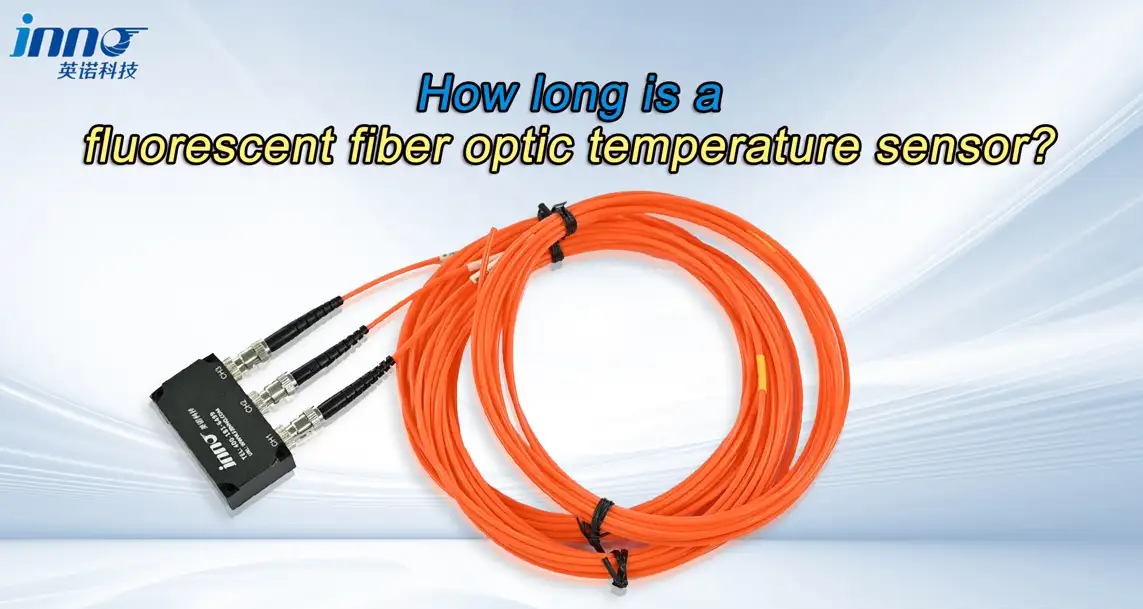
For many electrical equipment and industrial temperature measurement applications, a fiber length of approximately 3-5 m is a practical starting point. The correct length, however, should be determined from the actual routing distance between the sensing point and the temperature monitoring instrument - not from the straight-line distance between them.
This guide focuses on fluorescence-based point fiber optic temperature sensors, where a single probe measures one defined temperature point through a fiber that connects the sensing tip to a monitoring instrument. Typical INNO point fiber optic temperature probe configurations can support approximately 0-20 m of fiber length, depending on probe structure and project requirements.
The right length depends on the measurement point, the instrument position, internal equipment routing, the feedthrough location, the bend path, installation allowance, and future service access.
Key Takeaways
- 3-5 m is a practical starting fiber length for many electrical equipment applications.
- Final fiber length should follow the real routing path rather than straight-line distance.
- Larger transformers, high-voltage test setups and remote instrumentation may require longer fiber runs.
- Small cabinets or compact equipment may require shorter probes.
- Different channels in one multi-channel monitoring system can use different fiber lengths.
- Fiber length, probe structure, channel quantity and monitoring instrument should be selected together.
Fiber Optic Temperature Sensor Length at a Glance
| Selection Item | Typical Direction | What to Check |
|---|---|---|
| Fiber Length | 3-5 m common starting range | Actual routing distance |
| Available Configuration | Approximately 0-20 m | Probe and project requirements |
| Small Equipment | Around 3 m may be sufficient | Cabinet size and instrument position |
| Transformer / Larger Equipment | 3-5 m or longer | Internal winding route and external instrument position |
| Laboratory / High-Voltage Testing | Application-specific | Distance between test object and monitoring equipment |
| Multi-Channel System | Different lengths possible | Each probe route independently |
These are practical selection references rather than fixed installation standards.
How Long Is a Fiber Optic Temperature Sensor?
There is no single fixed length. For many equipment applications, 3-5 m is common, and INNO point fiber optic temperature probes can be configured from approximately 0 to 20 m depending on probe construction and project requirements.
It helps to separate three different measurements:
- Probe tip length - the small sensing element at the measurement point.
- Fiber length - the optical fiber running from the probe tip to the monitoring instrument.
- Total assembly length - the combined length of the probe, fiber and any connectors.
When buyers ask "How long is the sensor?", they usually mean the optical fiber length between the sensing probe and the monitoring instrument, since this determines how the probe can be routed and installed.
Why Are 3-5 m Fiber Lengths Common?
3-5 m is a practical starting range for many installations because the distance between a sensing point and a monitoring instrument in transformers, switchgear, electrical cabinets, motors, generators and test equipment often includes both internal and external routing.
A length in this range can typically accommodate internal routing inside the equipment, the path to a feedthrough or gland, routing across a cabinet to the monitoring instrument, the final connection, and a reasonable installation allowance for bends and service access.
3-5 m is not an industry standard - it is simply a length that covers many common routing distances without excess fiber.
How Should Fiber Length Be Calculated?
Fiber length should not be measured only as the straight-line distance between the sensing point and the instrument. A practical way to estimate the required length is:
Required fiber length = internal routing + distance to feedthrough + external routing + installation allowance
In practice, this means working through the route step by step:
- Distance from the sensing point to the equipment exit.
- Internal bends and routing inside the equipment.
- Position of the feedthrough or gland.
- Distance from the equipment exit to the monitoring instrument.
- Extra allowance for service, maintenance access and future adjustment.
Do not measure only from the probe tip to the instrument in a straight line.
3 m vs 5 m: Which Fiber Length Should You Choose?
| Selection | 3 m Fiber | 5 m Fiber |
|---|---|---|
| Small Cabinet | Often sufficient | Extra length usually unused |
| Transformer Internal Routing | May be tight for longer internal paths | Provides more routing margin |
| Instrument Installed Nearby | Well matched | Often more than needed |
| Additional Routing Margin | Limited | More flexibility for bends and feedthroughs |
| Large Equipment | May be insufficient | Better suited |
| Test Setup | Suitable for compact layouts | Suitable when the instrument sits farther away |
A 3 m fiber may be suitable for compact equipment where the monitoring instrument is close to the sensing point. A 5 m fiber provides additional routing flexibility for transformers, larger cabinets and equipment where the instrument is mounted farther away. Choose based on routing, not simply because longer is better.
How to Choose Fiber Length for Transformer Temperature Measurement
For a transformer fiber optic temperature sensor, the fiber length depends on the winding sensing point, the transformer dimensions, the distance from the winding to the feedthrough, the internal fiber route, the tank exit, the monitoring instrument position, and service allowance.
For many transformer applications, approximately 3-5 m is a useful starting reference, but larger transformers or longer internal routing paths may require additional length. Values such as "oil transformer = 5 m" or "dry transformer = 3 m" should not be treated as fixed rules - they are only starting points until the actual route is measured.
How to Choose Fiber Length for Dry-Type Transformers
For dry-type transformers, the fiber length depends on the phase or winding measurement location, the controller position, the internal transformer frame, the routing along the winding or structure, and the available mounting position.
Dry-type transformer installations often allow the monitoring controller to be mounted relatively close to the transformer, so 3-5 m probes are frequently practical. Actual routing should still be measured before final selection.
How to Choose Fiber Length for Oil-Immersed Transformers
Oil-immersed transformer applications may require longer internal routing because the sensing probe can be positioned at selected winding locations, and the optical fiber must route toward a suitable feedthrough before reaching the external monitoring instrument.
Key factors include the winding point, the internal lead route, the fiber feedthrough, tank dimensions, and the external monitoring cabinet location. 3-5 m may be sufficient for some designs, while larger transformers can require longer customized fiber lengths.
How to Choose Fiber Length for Switchgear and Busbar Temperature Monitoring
Switchgear temperature monitoring typically focuses on busbar joints, cable terminations, contacts and other selected connection points. Fiber length depends on the sensing point position, cabinet dimensions, the monitoring instrument location, and the fiber routing between compartments.
Around 3 m can be practical for compact cabinets, while larger or multi-compartment switchgear may require longer routing. 3 m should not be treated as a fixed value for every design.
How to Choose Fiber Length for Motors and Generators
For motor winding temperature sensor and generator winding temperature monitoring applications, fiber length should account for the winding or stator measurement point, machine dimensions, the fiber exit route, the terminal area, and the external monitoring instrument position.
Larger generators may require longer fiber routing than compact motors, but there is no single fixed length that applies to every machine size.
How to Choose Fiber Length for High-Voltage Testing
In high voltage temperature measurement setups, fiber length has an additional purpose: it allows the monitoring instrument to remain at a physical distance from the high-voltage test object.
Relevant factors include the test object position, a safe instrument location, routing around test equipment, test platform size, the measurement point, and cable management. Longer fiber lengths may be useful when the monitoring instrument must remain outside the immediate high-voltage test area.
How to Choose Fiber Length for RF and Microwave Equipment
For RF temperature sensor and microwave temperature measurement applications, the fiber length should allow the temperature probe to remain at the measurement point while the monitoring instrument is positioned outside or away from the RF or microwave field when required.
Factors to check include microwave chamber dimensions, probe entry location, instrument location, fiber routing, and mechanical protection along the route.
How to Choose Fiber Length for Laboratory and Test Equipment
Laboratory temperature monitoring setups are typically more flexible than fixed installations. A laboratory environment may involve a short bench setup, a high-voltage experiment, multiple test objects, a thermal chamber, or an RF experiment.
Key factors include the test object location, the instrument bench position, equipment movement, and routing flexibility. Laboratory applications may use anything from short probes to considerably longer customized fiber runs depending on the test layout.
Typical Fiber Length Selection by Application
| Application | Practical Starting Direction | Main Factors |
|---|---|---|
| Small Electrical Cabinet | Around 3 m | Cabinet dimensions, nearby instrument |
| Dry-Type Transformer | 3-5 m | Winding location, controller position |
| Oil-Immersed Transformer | 3-5 m or longer | Internal winding route, feedthrough, tank dimensions |
| Switchgear / Busbar | Around 3-5 m | Cabinet compartments, connection points |
| Motor / Generator | Application-specific | Machine size, winding location, external instrument |
| High-Voltage Testing | Often longer if required | Distance between test object and monitoring equipment |
| RF / Microwave | Application-specific | Chamber size and instrument location |
| Laboratory / Test Bench | Application-specific | Bench layout and routing |
These values are initial selection references, not mandatory lengths.
Is a Longer Fiber Always Better?
No. A longer-than-necessary fiber can add unnecessary routing, make installation less tidy, require additional fiber management, and increase the amount of unused fiber inside cabinets or equipment.
Choose enough length for the actual route plus reasonable installation allowance, rather than simply selecting the longest available option.
Does Fiber Length Affect Temperature Measurement Accuracy?
For properly designed point fiber optic temperature sensing systems, fiber length within the supported configuration is not selected primarily to change the temperature measurement range or accuracy. The probe and monitoring instrument should be specified as a complete, compatible measurement system.
This does not mean fiber length is irrelevant in every possible scenario - it means buyers should use fiber lengths supported by the selected probe and instrument configuration, rather than assuming any arbitrary length will behave identically.
Does Fiber Length Affect Response Time?
Temperature response is primarily related to the sensing tip, probe structure, thermal contact, and application conditions. Within the supported system configuration, fiber length is normally selected mainly for routing rather than thermal response, and longer fiber does not automatically mean slower temperature response in a correctly specified system.
Can Different Channels Use Different Fiber Lengths?
Yes. In a multi-channel fiber optic temperature monitoring system, each channel is connected to an independent probe, so one channel may use a 3 m probe, another may use a 5 m probe, and a third may use a longer customized probe - as long as each probe is compatible with the selected monitoring instrument.
Channel quantity and fiber length are independent selection parameters.
Fiber Length vs Number of Monitoring Channels
These two parameters answer different questions:
- Fiber length - how far is the sensing point from the monitoring instrument?
- Channel quantity - how many independent temperature points can be monitored?
For example, a 6-channel monitoring system with 6 probes could be configured with individual lengths such as 3 m, 3 m, 5 m, 5 m, 8 m and 8 m, matched to each sensing point's actual route. This is only an illustration of how lengths can vary by channel, not a fixed product combination.
Can Fiber Length Be Customized?
Yes. Fiber length can be selected according to equipment dimensions, the installation route, instrument position, sensing point location, test setup, and special project requirements.
INNO point temperature probes can typically be configured within approximately 0-20 m. For lengths outside standard offerings, confirm the requirement with engineering before placing an order.
How to Choose the Right Fiber Length in Five Steps
- Locate the sensing point.
- Locate the temperature monitoring instrument.
- Measure the actual routing path - not the straight-line distance.
- Include bends, feedthroughs and installation allowance.
- Confirm the final fiber length with the probe and monitoring instrument configuration.
3 m, 5 m or Longer: Quick Selection Guide
| Situation | Initial Direction |
|---|---|
| Compact cabinet with nearby instrument | Around 3 m |
| Transformer / larger cabinet | 3-5 m |
| Long internal transformer route | 5 m or longer |
| High-voltage test object with remote instrument | Longer customized fiber |
| RF / microwave chamber | Based on probe entry and instrument location |
| Laboratory test bench | Based on test layout |
Always measure the actual routing path before finalizing the probe length.
What Information Is Needed to Select the Fiber Length?
- Equipment type
- Measurement point
- Probe location
- Monitoring instrument location
- Straight-line distance
- Actual routing distance
- Internal equipment routing
- Feedthrough location
- Required installation allowance
- Probe dimensions
- Number of sensing points
- Number of channels
- Operating environment
- High-voltage / EMI / RF conditions
- Required connector
- Extension cable requirement
Common Fiber Length Selection Mistakes
- Measuring only the straight-line distance. This ignores internal routing, bends and feedthroughs that add real length to the run.
- Forgetting internal routing inside the equipment. Space between the sensing point and the equipment exit is often overlooked.
- Selecting the longest available fiber without a routing reason. This leaves excess fiber to manage without a practical benefit.
- Using the same fiber length for every channel without checking individual measurement points. Each sensing point can have a different route.
- Confirming fiber length without confirming connector and monitoring instrument compatibility. Length is only one part of a compatible measurement system.