
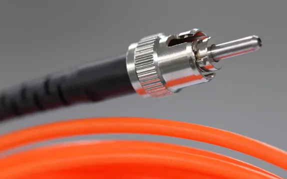
For point fiber optic temperature monitoring, one probe normally measures one defined temperature location and occupies one measurement channel. If six temperature points need to be monitored at the same time, the system generally requires at least six active channels.
Channel selection is not only a matter of counting probes. Different equipment types use very different measurement-point arrangements. Switchgear, box-type substations, dry-type transformers, oil-immersed transformers, power electronic equipment and laboratory test systems may require anything from a few channels to a much larger customized multi-channel configuration.
Fiber optic temperature sensors are particularly useful in equipment where high voltage, electrical isolation or strong electromagnetic interference must be considered. The optical sensing path is electrically isolated and immune to electromagnetic interference, while the monitoring instrument can be configured around the actual number of temperature points.
For most projects, channel selection can be reduced to four questions:
- How many physical temperature points need to be measured?
- Which points need to be monitored simultaneously?
- Are spare channels needed for future expansion?
- What monitoring, communication and alarm functions are required?
Key Takeaways
- One point fiber optic temperature probe normally uses one independent measurement channel.
- The required channel quantity should follow the number of temperature points monitored simultaneously.
- Several probes can connect to one multi-channel fiber optic temperature monitoring instrument.
- Common channel configurations vary significantly between switchgear, dry-type transformers, oil-immersed transformers and test equipment.
- Spare channels can be useful when additional sensing points may be added later.
- The number of channels should be confirmed before selecting the temperature transmitter or monitoring instrument.
Fiber Optic Temperature Monitoring Channel Selection at a Glance
| Measurement Points | Minimum Active Channels | Typical System Direction |
|---|---|---|
| 1 point | 1 channel | Single-channel or compact monitoring unit |
| 2 points | 2 channels | 2-channel or higher-capacity instrument |
| 4 points | 4 channels | 4-channel monitoring instrument or OEM module |
| 6 points | 6 channels | Multi-channel monitoring instrument |
| 8 points | 8 channels | 8-channel monitoring system |
| 12 points | 12 channels | 12-channel multi-point monitoring system |
| 16 points | 16 channels | Higher-channel transformer or equipment monitoring system |
| Special applications | 1–64 channels | Customized configuration according to measurement points |
These are system-selection directions rather than fixed industry requirements. The final channel count should match the actual number of sensing points, equipment layout and monitoring objective.
What Does a Temperature Monitoring Channel Mean?
A channel is one independent measurement input on the temperature transmitter or monitoring instrument. For point fiber optic temperature measurement, the relationship is straightforward:
One probe → one sensing point → one measurement channel
For example, six optical temperature probes installed at six independent locations normally require six active measurement channels. The probes may have different fiber lengths and may be installed at different parts of the same piece of equipment.
Start by Counting the Actual Temperature Measurement Points
Do not begin by asking whether you need a 4-channel, 8-channel or 16-channel instrument. Begin with the equipment and identify the locations that actually require temperature measurement.
Typical examples include:
- Transformer winding hot-spot locations
- Busbar joints
- Cable termination points
- Switch contacts
- Motor or generator winding locations
- IGBT or power electronic module measurement points
- High-voltage test objects
- RF or microwave test positions
If all of these locations must be monitored simultaneously, the number of active channels should normally equal the number of installed point probes.
How Many Channels Are Commonly Used for Switchgear and Box-Type Substations?
Switchgear and box-type substations often require multi-point monitoring because one cabinet may contain several important electrical connections. Typical locations include busbar joints, cable terminations, contacts and other selected connection points.
Common fiber optic temperature monitoring configurations for these applications include:
- 3 channels
- 6 channels
- 9 channels
- 12 channels
The final configuration depends on how many electrical connection points need simultaneous measurement.
For example, if three phases each require temperature measurement at two selected connection points, six probes and six active channels may be used. If three locations are monitored on each phase, a 9-channel arrangement may be considered.
These are practical configuration examples rather than fixed requirements for every switchgear cabinet or box-type substation.
How Many Channels Are Commonly Used for Dry-Type Transformers?
Dry-type transformer temperature monitoring is often organized around phase and winding measurement points. Depending on the transformer structure and monitoring objective, common fiber optic temperature controller configurations include:
- 3 channels
- 4 channels
- 6 channels
- 7 channels
A 3-channel system may be used where one temperature point is monitored for each phase. Additional channels can be selected when more winding positions, auxiliary temperature points or other monitoring locations need to be included.
The channel count should therefore follow the actual winding-temperature measurement plan rather than simply the number of transformer phases.
How Many Channels Are Commonly Used for Oil-Immersed Transformers?
Oil-immersed transformer projects often use more measurement points because optical probes may be embedded at selected winding locations across several phases, winding sections or identified hot-spot areas.
Common multi-channel configurations include:
- 6 channels
- 8 channels
- 9 channels
- 12 channels
- 16 channels
The final number depends on:
- Number of phases
- Number of monitored windings
- Selected internal temperature locations
- Transformer winding arrangement
- Monitoring objectives
- Available probe locations
For example, if eight independent internal fiber optic probes are installed, the monitoring system requires at least eight active measurement channels.
An oil-immersed transformer does not automatically require 8, 12 or 16 channels. These are common configuration patterns, while the actual requirement must follow the transformer design.
How Many Channels Are Needed for Motors and Generators?
Motors and generators may require measurement at several stator or winding locations. The required channel count follows the number of positions that must be monitored independently.
For example:
- 3 winding locations → 3 channels
- 6 stator measurement points → 6 channels
- 9 independently monitored points → at least 9 channels
The exact arrangement depends on phase structure, winding layout and the temperature locations selected by the equipment manufacturer.
Channel Selection for IGBT, Test Equipment and Special Applications
Special applications do not always follow the channel patterns used for transformers or switchgear. IGBT modules, power electronics, high-voltage experiments, laboratory equipment, RF systems and microwave test setups may require only one or two measurement points, or they may require dozens of simultaneous temperature channels.
Typical applications include:
- IGBT and power electronic modules
- High-voltage test equipment
- Laboratory experiments
- RF and microwave equipment
- Industrial heating equipment
- Research test benches
- Custom electrical equipment
For these applications, fiber optic temperature monitoring systems can be customized from approximately 1 to 64 channels, with additional expansion considered for special project requirements.
This allows the monitoring architecture to be designed around the actual number of probes instead of forcing the equipment into a fixed channel configuration.
Common Fiber Optic Temperature Monitoring Channel Configurations
| Application | Common Channel Configurations | What Determines the Final Channel Count |
|---|---|---|
| Switchgear / Electrical Cabinet | 3 / 6 / 9 / 12 | Number of busbar joints, cable connections and contacts |
| Box-Type Substation | 3 / 6 / 9 / 12 | Number of selected electrical connection points |
| Dry-Type Transformer | 3 / 4 / 6 / 7 | Phase and winding temperature measurement points |
| Oil-Immersed Transformer | 6 / 8 / 9 / 12 / 16 | Winding arrangement, phases and selected internal sensing locations |
| Motor / Generator | Customized | Number of stator or winding measurement positions |
| IGBT / Power Electronics | Customized | Number of semiconductor or module measurement points |
| Laboratory / Test Equipment | 1–64 customized | Number of test objects and simultaneous measurement points |
These channel counts represent common application patterns rather than mandatory configurations. Final channel quantity should always be selected according to the actual number of probes and required monitoring functions.
Should You Reserve Spare Channels?
Spare channels can be useful when additional measurement points may be added later. They are particularly worth considering when the equipment design is not final, future expansion is planned, or one monitoring instrument may eventually serve additional temperature probes.
For example, if the current project requires six active measurement points but two more probes may be added later, an 8-channel instrument can be considered.
This is a planning example rather than a universal rule. A system does not need unused channels simply for the sake of having spare capacity.
Can Multiple Pieces of Equipment Share One Monitoring Instrument?
Yes. Several pieces of equipment can share one multi-channel monitoring instrument when the total probe quantity is within the available channel capacity and the fiber routing is practical.
For example:
4 cabinets × 2 probes per cabinet = 8 temperature points = 8 active channels
Before using one host instrument for several pieces of equipment, confirm:
- Total number of probes
- Distance between equipment
- Fiber length for each sensing point
- Monitoring instrument location
- Equipment grouping
- Communication requirements
- Alarm requirements
Channel Count and Fiber Length Are Different Parameters
Channel quantity determines how many independent temperature points can be measured. Fiber length determines the routing distance between each sensing point and the monitoring instrument.
An 8-channel monitoring unit can therefore connect eight probes with different fiber lengths. One probe may require 3 m of fiber while another may require 5 m or longer, depending on the equipment layout.
For many electrical equipment installations, approximately 3–5 m is a practical starting fiber length, but the final length should follow the actual routing path rather than straight-line distance.
How Channel Count Affects Monitoring Instrument Selection
The probe quantity should normally be confirmed before selecting the fiber optic temperature transmitter or monitoring instrument.
| Requirement | Typical Monitoring Direction |
|---|---|
| 1–4 sensing points | Compact transmitter or OEM temperature module |
| 3–7 dry-type transformer points | Transformer-oriented multi-channel temperature controller |
| 6–16 transformer or electrical equipment points | Multi-channel monitoring instrument |
| Large customized systems | 1–64 channel customized monitoring configuration |
| Local temperature display | Monitoring instrument with integrated display |
| PLC / SCADA integration | Instrument with required industrial communication interface |
| Alarm control | Instrument with relay outputs where required |
What Outputs Should Be Considered with Multi-Channel Monitoring?
Channel quantity only defines measurement capacity. The monitoring system must also provide the required data and control interfaces.
Depending on the selected monitoring instrument, available functions may include:
- RS485
- Modbus RTU
- 4–20 mA analog output
- Alarm relay output
- Local temperature display
- PLC communication
- SCADA integration
Not every instrument provides the same output combination, and an individual 4–20 mA output should not be assumed for every channel unless the selected model supports it.
A Simple Way to Calculate the Required Channel Count
Required active channels = Number of independent temperature points measured simultaneously
If future expansion is planned:
Recommended instrument capacity = Required active channels + optional spare capacity
Examples:
- 4 installed probes → 4 active channels
- 6 installed probes + 2 planned future points → an 8-channel system may be considered
- 12 independent probes → at least 12 active channels
- 32 laboratory measurement points → a 32-channel or suitable larger customized system can be selected
Typical Channel Selection by Application
| Application | Typical Channel Direction | Selection Basis |
|---|---|---|
| Switchgear | 3 / 6 / 9 / 12 | Busbar joints, contacts and cable terminations |
| Box-Type Substation | 3 / 6 / 9 / 12 | Selected electrical connection points |
| Dry-Type Transformer | 3 / 4 / 6 / 7 | Phase and winding temperature points |
| Oil-Immersed Transformer | 6 / 8 / 9 / 12 / 16 | Internal winding and hot-spot measurement positions |
| Motor / Generator | According to measurement points | Stator and winding locations |
| IGBT / Power Electronics | 1 channel upward | Number of module or device sensing points |
| High-Voltage Test Bench | Customized | Number of test points monitored simultaneously |
| Laboratory / RF / Microwave | 1–64 customized | Number of test objects and sensing locations |
Why Multi-Channel Fiber Optic Monitoring Is Useful in Electrical Equipment
Multi-channel fiber optic temperature monitoring is particularly useful when several measurement points are located inside high-voltage equipment or strong electromagnetic environments.
The optical probes provide an electrically isolated sensing path and are immune to electromagnetic interference along the optical link. Multiple probes can therefore be routed from selected sensing locations to one monitoring instrument without requiring an electrical temperature signal at each measurement point.
This makes the system suitable for complex multi-point measurement arrangements in transformers, switchgear, generators, power electronics, high-voltage testing and other electrically sensitive equipment.
Common Channel Selection Mistakes
Choosing the monitoring instrument before counting the measurement points. The number of required probes should normally be confirmed first.
Assuming one piece of equipment needs only one channel. One transformer, switchgear cabinet or generator may contain several important measurement points.
Treating common channel counts as fixed standards. A 6-channel transformer system or 9-channel switchgear system is only one possible configuration.
Confusing channel quantity with fiber length. These are independent parameters.
Selecting enough channels but ignoring outputs. RS485, Modbus, analog output, alarm relay and local display requirements should be confirmed together with the channel count.
What Information Is Needed to Select the Number of Channels?
Before selecting a fiber optic temperature monitoring system, prepare the following information:
- Equipment type
- Number of equipment units
- Number of temperature points per unit
- Total number of probes
- Points requiring simultaneous monitoring
- Future expansion requirements
- Required spare channels
- Fiber length for each probe
- Monitoring instrument location
- Local display requirement
- RS485 / Modbus requirement
- 4–20 mA requirement
- Alarm relay requirement
- PLC / SCADA integration requirement
- OEM integration requirement