
Transformer hot spots are localized areas of the winding or nearby current-carrying structure that operate at a higher temperature than the surrounding transformer. They are created by the combination of electrical losses, current distribution, winding geometry and local cooling conditions.
Hot-spot temperature matters because a single top-oil or average temperature value may not represent the hottest part of the winding. The temperature distribution inside a transformer is not uniform, and the local peak is what drives thermal stress and insulation aging.
Transformer hot spots can be monitored indirectly through thermal models or winding temperature indicators, or directly at selected locations using embedded fiber optic temperature sensors. This guide explains what causes hot spots, why measured values differ, and how each monitoring method works.
Key Takeaways
- Transformer hot spots are localized high-temperature regions, not the average transformer temperature.
- Electrical losses and uneven cooling are major contributors to hot-spot formation.
- Hot-spot location depends on transformer design and operating conditions.
- Top-oil temperature alone does not directly measure winding hot-spot temperature.
- WTI and thermal models estimate winding or hot-spot temperature from other measured variables.
- Embedded point fiber optic sensors can directly measure selected winding locations.
What Is a Transformer Hot Spot?
A transformer hot spot is the localized area within the transformer that reaches a higher temperature than surrounding winding or oil regions. It is a local value, not a description of the whole winding.
A winding can have an average temperature that appears acceptable while one localized region operates at a higher temperature. The two values describe different things: the average shows overall thermal condition, and the hot spot shows the critical local temperature. A localized hot spot can exist under normal operation because heat generation and cooling are not perfectly uniform. Whether the temperature is acceptable depends on the transformer design, loading and applicable operating limits, and hot-spot temperature is closely related to insulation thermal aging.
Where Do Transformer Hot Spots Occur?
Possible hot-spot areas may include:
- Selected winding turns
- Winding sections with higher local losses
- Areas with restricted oil circulation
- Conductor transposition or structural regions
- Winding leads or electrical connections
- Other current-carrying locations, depending on design
There is no universal fixed hot-spot location for every transformer. The likely position depends on winding geometry, current distribution, load, losses, cooling and oil flow, and it is normally determined from the transformer design and thermal analysis. The location can also shift with operating condition.
What Causes Hot Spots in Transformers?
Load Current and I2R Losses
As load current increases, conductor losses increase and winding temperature rises. Because load losses are generated in the conductors, windings are a primary region for elevated temperature, although other current-carrying connections or structures can also develop localized heating.
Eddy Current and Stray Losses
Local electromagnetic conditions can create additional losses in conductors and in nearby metallic structures. These losses are not spread evenly, so they add heat to some regions more than others.
Uneven Cooling
Heat removal is rarely uniform. Contributing factors include:
- Oil flow distribution
- Cooling duct effectiveness
- Local airflow in dry-type transformers
- Cooling equipment operation
Winding Geometry and Current Distribution
Different winding sections may not generate or dissipate heat uniformly. Conductor arrangement, section position and current distribution all influence where heat concentrates.
Overload or High Operating Load
Higher loading increases thermal stress on the insulation system. Operation above rated load is a thermal loading condition to be managed, and it does not mean immediate damage.
Local Connection or Contact Heating
A high-resistance connection or current-carrying joint can create localized heating. This is one possible contributor among several and is usually treated separately from normal winding heating.
Why Is Hot-Spot Temperature Different from Average Winding Temperature?
Averaging smooths out the temperature distribution. Several temperature values are used in transformer thermal monitoring, and each represents something different:
- Ambient temperature: the surrounding air temperature.
- Top-oil temperature: the temperature of transformer oil near the upper region of the tank or at a designated measurement location.
- Average winding temperature: the average temperature of the winding conductors or winding mass.
- WTI value: usually an estimated or simulated winding temperature, derived from oil temperature plus load-current-related compensation, depending on instrument design.
- Hot-spot temperature: the localized maximum or near-maximum winding temperature at a specific critical location.
- Direct fiber optic temperature: the actual temperature at the physical probe location.
| Temperature Value | What It Represents | Main Limitation |
|---|---|---|
| Average Winding Temperature | Average conductor temperature | May hide local peaks |
| Top-Oil Temperature | Oil temperature at a defined location | Does not directly equal winding hot spot |
| WTI Reading | Estimated winding temperature | Depends on model and compensation method |
| Direct Fiber Optic Reading | Temperature at the probe location | Represents only the installed point |
Does Top-Oil Temperature Show the Transformer Hot Spot?
No, not directly. Top-oil temperature gives useful information about transformer thermal condition, but it is not the same as winding hot-spot temperature.
The winding hot spot can differ significantly from the oil temperature, depending on loading, winding design, thermal gradient and cooling conditions. The size of that difference is specific to each transformer and operating state, so it should not be treated as a fixed offset.
How Is Transformer Hot-Spot Temperature Estimated?
Traditional methods combine measured values with calculation. They typically use:
- A winding temperature indicator
- A thermal model
- Load current
- Top-oil temperature
- A calculated thermal gradient
These methods estimate the hot-spot or winding temperature rather than directly measuring the conductor at the hottest physical location. Estimation remains widely used and can be effective for transformer monitoring when it is correctly configured.
How Does a Winding Temperature Indicator Estimate Hot-Spot Temperature?
A winding temperature indicator (WTI) generally simulates or estimates winding temperature. The typical logic combines oil temperature with a load-current-related thermal compensation. The instrument adds a calculated temperature increment, based on current, to the oil temperature reading.
A conventional WTI typically does not directly measure the winding conductor temperature. Its accuracy depends on how well the compensation matches the actual transformer. The related oil temperature indicator (OTI) measures oil temperature only.
How Do Thermal Models Estimate Transformer Hot Spots?
Thermal models use measured and calculated inputs, such as load, current, oil temperature, thermal constants and transformer design parameters, to estimate winding or hot-spot temperature.
Advantages: no embedded winding sensor is required, and the model supports continuous condition monitoring.
Limitations: the output depends on model assumptions, transformer parameters, input accuracy and operating conditions. A model is only as representative as its inputs.
How Can Fiber Optic Sensors Directly Monitor Transformer Hot Spots?
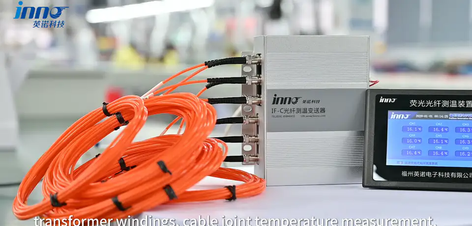
Fiber optic probes can be installed at selected winding locations during transformer manufacturing. The measurement chain is simple:
Fiber Optic Probe → Optical Fiber → Temperature Monitoring Instrument → Temperature Data
The probe directly measures the temperature at its installed physical location; that location represents a hot-spot candidate only when it has been selected from the transformer design and thermal analysis. Its advantages are direct point measurement, an electrically isolated sensing path, EMI immunity along the optical path, suitability for high-voltage winding environments, and the option to measure several points.
The sensor does not automatically locate the hot spot. Probe placement must be selected beforehand, so the reading is only as representative as the position chosen.
INNO provides point fiber optic temperature probes and multi-channel monitoring instruments for direct temperature measurement at selected transformer winding locations, using fluorescence-based point fiber optic temperature sensing. Typical values are approximately -40 to 260 °C temperature range, approximately ±0.5 to ±1 °C accuracy, response under 1 s and approximately 0-20 m fiber length, all depending on configuration and project requirements.
Where Should Fiber Optic Temperature Sensors Be Placed in Transformer Windings?
Placement should follow the transformer design, the predicted hot-spot location, thermal calculation, winding geometry, cooling design and manufacturer experience. Multiple probes may be placed at several candidate hot-spot regions rather than at one assumed position.
Why Use Multiple Temperature Sensors Instead of One?
One probe equals one physical point, and a single point cannot represent the temperature distribution of an entire winding. Multi-point monitoring can provide:
- Comparison between winding locations
- Thermal distribution information
- Identification of higher-temperature regions
- Redundancy and cross-checking
- Better understanding under different loads
More sensors are not automatically better. Channel quantity should be based on transformer design and monitoring objectives.
How Many Fiber Optic Channels Are Used for Transformer Hot-Spot Monitoring?
For INNO projects, common oil-immersed transformer configurations may include 6 / 8 / 9 / 12 / 16 channels, depending on transformer design, number of windings, number of phases, selected sensing points and project requirements. These are practical configuration patterns, not industry-mandated channel counts. Additional customized channels may be possible depending on the instrument.
Direct Hot-Spot Measurement vs Estimated Hot-Spot Temperature
| Method | Measurement Basis | Direct or Estimated | Main Advantage | Main Limitation |
|---|---|---|---|---|
| Top-Oil Sensor | Oil temperature | Direct oil measurement | Simple thermal reference | Not a direct winding hot spot |
| WTI | Oil temperature + load compensation | Estimated | Widely used | Depends on simulation and configuration |
| Thermal Model | Load + oil + transformer parameters | Estimated | Continuous calculated hot-spot estimate | Depends on model inputs |
| Embedded Fiber Optic Sensor | Probe at a selected winding location | Direct point measurement | Measures the actual installed location | Only measures the selected probe location |
Each method provides different thermal information, and many transformer monitoring architectures use more than one.
Can Fiber Optic Sensors Replace Winding Temperature Indicators?
Not necessarily in every project. Fiber optic sensors and WTI serve different roles. A fiber optic probe gives direct physical point measurement, while a WTI gives an estimated winding temperature based on thermal simulation and compensation. Some projects use both, and the choice depends on the transformer specification, user practice and monitoring goals.
What Happens When Transformer Load Changes?
As load changes, conductor losses change. Oil temperature generally changes more slowly, so winding temperature may respond differently from oil temperature, and local hot-spot temperature may change as well. Both the location and the magnitude of the hot spot can vary with operating condition, which is why a reading at one load level should not be assumed to hold at another.
How Does Cooling Affect Transformer Hot Spots?
Cooling strongly influences how heat is removed from the windings, oil, core and structures. Relevant factors include natural oil circulation, forced oil circulation, fan operation, pump operation, cooling ducts and airflow. Uneven or insufficient local heat removal can contribute to higher local temperature, even when overall oil temperature looks normal.
How Are Hot Spots Monitored in Oil-Immersed Transformers?
Common monitoring combines several of the following:
- Top-oil temperature
- WTI
- Thermal model
- Embedded fiber optic sensors
- Transformer monitoring system
Embedded fiber optic probes are often installed during transformer manufacturing. Retrofitting sensors directly into internal winding positions is generally much more difficult after the transformer is built, so the decision is best made at the design stage.
How Are Hot Spots Monitored in Dry-Type Transformers?
Dry-type transformers do not use insulating oil, so monitoring focuses on windings, coils, the core and selected structural locations. PT100 / RTD sensors are common. Fiber optic sensors may be used when electrical isolation, EMI immunity or direct selected-point measurement is required. Both approaches are valid, and the choice depends on the design and the monitoring requirement.
How Can Transformer Hot-Spot Data Be Integrated into a Monitoring System?
The fiber optic monitoring instrument or transformer monitoring device can use the data for local display, alarms, trend recording, PLC, SCADA or a transformer condition monitoring platform. Possible integration options include RS485 with a supported protocol such as Modbus RTU, 4-20 mA, alarm relay and Ethernet / TCP/IP, depending on the selected instrument. Not every model supports every interface, so confirm the required outputs at the specification stage.
What Should Be Monitored Alongside Transformer Hot-Spot Temperature?
Depending on transformer type and project, hot-spot temperature may be monitored together with:
- Top-oil temperature
- Winding temperature
- Load current
- Ambient temperature
- Cooling system status
- Oil condition / DGA
- Bushing condition
- Partial discharge
- OLTC condition
Hot-spot temperature is one part of transformer condition monitoring, and it is most useful when read alongside these other parameters.
What Information Is Needed to Plan Transformer Hot-Spot Monitoring?
- Transformer type
- Oil-immersed or dry-type
- Transformer rating
- Number of phases
- Winding arrangement
- Expected hot-spot locations
- Number of sensing points
- Required channels
- Probe installation stage
- Fiber routing
- Monitoring instrument location
- Required communication interface
- PLC / SCADA requirement
- Alarm requirement
Typical Transformer Hot-Spot Monitoring Architecture
Architecture 1: Top-Oil Sensor → WTI / Monitoring Device → SCADA
Architecture 2: Transformer Load + Oil Temperature → Thermal Model → Estimated Hot-Spot Temperature
Architecture 3: Embedded Fiber Optic Probes → Multi-Channel Temperature Monitor → PLC / SCADA / Transformer Monitoring System
These methods can also be combined in one monitoring architecture, with each supplying a different view of the thermal state.
Common Transformer Hot-Spot Monitoring Misunderstandings
1. The top-oil temperature is the winding hot-spot temperature.
No. They represent different thermal locations.
2. A winding temperature indicator directly measures winding conductor temperature.
A traditional WTI generally estimates or simulates winding temperature.
3. The transformer hot spot is always at the same physical location.
Location depends on design and operating conditions.
4. One fiber optic probe measures the entire winding.
One point probe measures one physical location.
5. Fiber optic sensors automatically find the hottest point.
Probe positions must be selected before operation.
6. More channels are always better.
Channel count should match the transformer design and monitoring objective.
7. Direct sensing makes thermal models unnecessary.
Direct and estimated methods can provide different information and may be used together.