
MRI & RF Fiber Optic Temperature Probe
Compact point temperature sensing for reviewed MRI, RF, NMR and medical research environments.
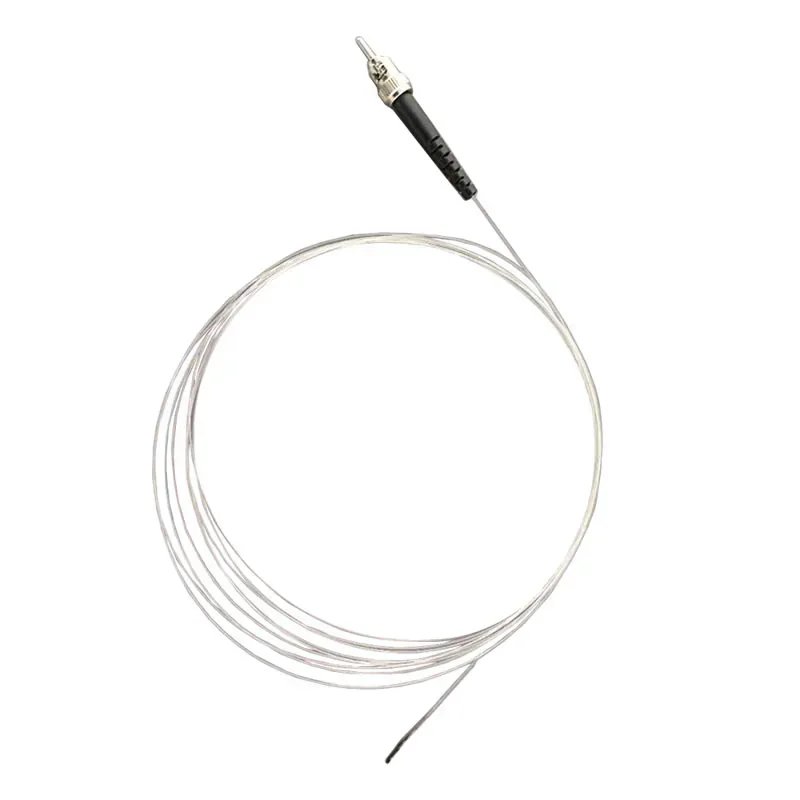
STRONG-FIELD TEMPERATURE PROBE
Use a Non-Conductive Optical Measurement Path in Strong Fields
This compact fluorescence probe is intended for application-specific measurement projects where metallic or electrically conductive sensor leads may be unsuitable around MRI, RF or NMR equipment.
The probe is not a medical device certification and does not operate alone. The full measurement setup, materials, placement and compatible instrument location must be application-specific for the specific equipment and procedure.
- Strong-field application review
- 1.5 mm sensing tip
- ±0.3 °C accuracy
- 5 m fiber length
Product Overview
The MRI and RF fiber optic temperature probe is a passive, non-conductive fluorescence probe for specialized projects around MRI, RF, NMR and related strong-field equipment. The standard configuration supports a 1.5 mm sensing tip, 5 m optical fiber, a 20 °C to 50 °C range and ±0.3 °C accuracy.
Application conditions in these environments vary substantially. The probe should therefore be evaluated as part of the complete measurement setup, including its position, materials, fiber route and the compatible signal-processing instrument.
SETUP REVIEW
Strong-Field Measurement Setup Review
The suitability of a temperature probe depends on the complete installation, not only on the sensing tip.
- Define the exact point to be measured.
- Review placement relative to the field and test arrangement.
- Confirm the selected instrument and fiber route for the project.
CONFIGURATION BOUNDARY
Defining Material and Instrument Position
The passive probe and the host instrument have different installation roles. Keep the instrument position and interface requirements explicit during planning.
- Use the standard configuration as a reference starting point.
- Confirm the required range and fiber length.
- Do not treat this page as a medical certification statement.
SHARED MEASUREMENT PRINCIPLE
Passive Point Sensing With a Compatible Instrument
The fluorescent sensing tip measures one selected point. A compatible instrument supplies the optical excitation, processes the returned signal and provides the temperature output. See the standard fluorescence probe for the full measurement principle.
PRODUCT CONSTRUCTION
Compact Strong-Field Probe Setup
The measurement setup is defined by the probe position, permitted materials, optical route and compatible instrument placement around the actual equipment.
Compact sensing tip
The listed 1.5 mm tip supports selected temperature points with limited available space.
Non-conductive optical path
Temperature information returns to the instrument optically rather than through a conductive sensor lead.
Separated instrument location
The compatible signal-processing instrument is positioned according to the complete test or research setup.
PRODUCT SELECTION
When to Choose the MRI & RF Probe
Choose this compact probe for research and equipment testing projects that require a passive optical sensing point around strong electromagnetic fields.
- MRI equipment development and testing
- RF and NMR research environments
- Medical-device thermal research
- Compact non-conductive sensing points
- Projects with a reviewed instrument location
APPLICATION-SPECIFIC ADVANTAGES
Key Probe Features
Strong-Field Application
The passive optical path suits application-specific MRI, RF and NMR measurement projects.
Compact Sensing Tip
A 1.5 mm sensing-tip diameter supports limited measurement spaces.
High-Resolution Configuration
The standard configuration supports ±0.3 °C accuracy and 0.01 °C resolution.
Non-Conductive Path
Temperature information returns optically to the instrument.
Fast Response
The collected probe configuration lists response within 100 ms.
Procedure-Specific Review
Materials, positioning and equipment compatibility must be assessed for each project.
TECHNICAL SPECIFICATIONS
Technical Specifications
Choose the final probe construction and compatible instrument for the application.
Parameters to Confirm Before Ordering
INSTALLATION PLANNING
Review the Complete Measurement Setup
The sensing tip must contact the actual temperature point while the optical route is protected through the equipment.
Target Point
Optical Route
Compatible Instrument
- Define the exact measurement point and acceptable probe materials.
- Confirm probe geometry, fiber route and compatible equipment access.
- Locate the signal-processing instrument according to the test setup.
- Validate the complete setup for the intended research or equipment procedure.
PRODUCT TO INDUSTRY
Typical Applications
Open the related industry or solution page for application-specific measurement and installation guidance.
RELATED PRODUCTS
Compatible Products for This Application
These products have different roles in the measurement path and are selected according to the installation.
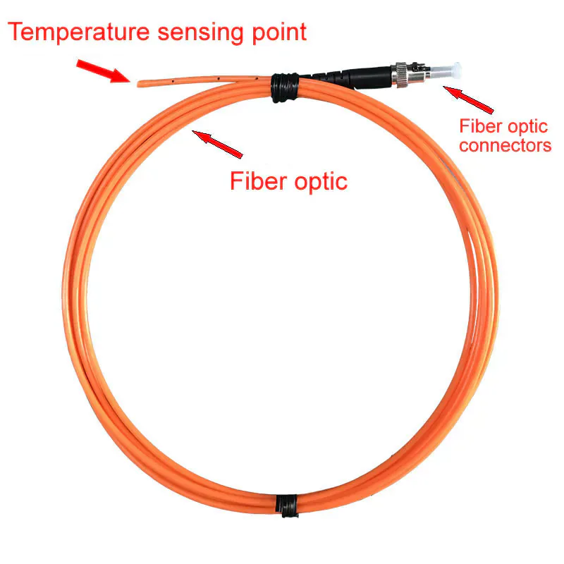
Standard Fluorescent Fiber Optic Temperature Probe
A configurable passive probe for general electrically demanding point measurements.
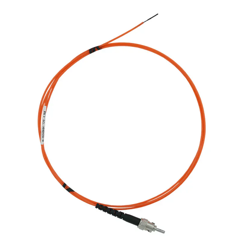
High- and Low-Temperature Fiber Optic Probe
A range-driven alternative for thermal test conditions.
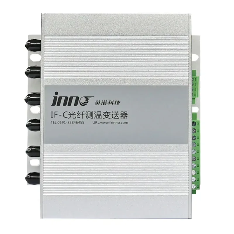
Multi-Channel Fiber Optic Temperature Transmitter
Provides compatible central processing when several points are required.
BUYER QUESTIONS
Frequently Asked Questions
Is this probe certified for every MRI procedure?
No. Compatibility and use must be evaluated for the specific equipment, procedure, materials and installation.
Is the probe itself a complete thermometer?
No. It is a passive sensing probe and requires a compatible fluorescence instrument.
What temperature range is listed?
The standard configuration supports +20 °C to +50 °C, with project configuration subject to confirmation.
Can the fiber length be changed?
The standard configuration supports 5 m and indicates configurable length. Final availability should be confirmed for the setup.
Does one probe measure multiple points?
No. One fluorescent sensing tip measures one point.
What project information should be provided?
Share the equipment type, procedure, temperature range, accuracy need, available space, fiber route and instrument location.
PROBE SELECTION SUPPORT
Review an MRI or RF Probe Configuration
Describe the equipment, measurement point, temperature range, available space, material constraints, fiber route and compatible instrument location.
- Measurement location
- Required temperature range
- Fiber route and length
Need Help Selecting the Correct Probe Construction?
Share the measurement point, environment and installation constraints with INNO.