
High- and Low-Temperature Fiber Optic Probe
Configurable probe construction for point measurement across demanding thermal and electrical test environments.
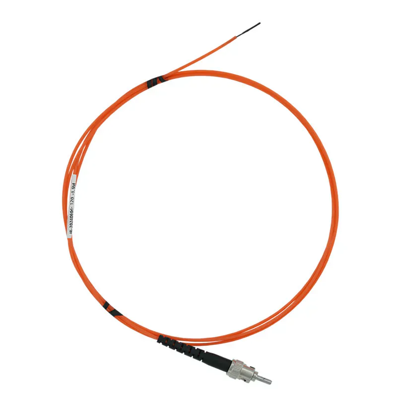
EXTENDED-RANGE POINT TEMPERATURE PROBE
Configure the Probe Around the Real Thermal Exposure
This probe family is intended for projects that need a application-specific temperature range, sensing-tip geometry, fiber length or protective sheath beyond a general-purpose installation.
The standard data must not be treated as a universal range for every construction. Confirm the complete thermal exposure, transition zones, mounting method and compatible instrument before selection.
- -40 °C to +260 °C standard range
- Higher-range configurations available for review
- 2.5 mm sensing tip
- Passive optical point sensor
Product Overview
The high- and low-temperature fiber optic probe is a configurable passive point probe for projects where the required temperature range or sheath construction needs more review than a standard configuration. The collected reference product lists a -40 °C to +260 °C standard range, with higher ranges and project-specific sheath options to be confirmed.
Temperature selection should consider the full installation path. The sensing tip may be at one thermal zone while the fiber route, connector position and compatible instrument are exposed to different conditions.
THERMAL DESIGN
Mapping Thermal Exposure Beyond the Sensing Tip
A reliable configuration begins with the thermal environment surrounding the entire probe assembly.
- Define the target measurement point.
- Identify exposure along the probe and fiber route.
- Separate standard values from project-confirmed options.
CONSTRUCTION REVIEW
Selecting Geometry and Sheath for the Test Setup
The installation method may drive the final construction as much as the temperature range itself.
- Review space, mounting and bend constraints.
- Confirm the final sheath and optical-fiber arrangement.
- Pair the probe with a compatible fluorescence instrument.
SHARED MEASUREMENT PRINCIPLE
Passive Point Sensing With a Compatible Instrument
The fluorescent sensing tip measures one selected point. A compatible instrument supplies the optical excitation, processes the returned signal and provides the temperature output. See the standard fluorescence probe for the full measurement principle.
PRODUCT CONSTRUCTION
Extended-Range Probe and Sheath Construction
The probe is selected around the temperature at the sensing tip and the separate thermal exposure along the fiber route.
Fluorescent sensing tip
The selected tip measures the target point while the construction is matched to the local thermal condition.
Configured sheath and lead
Sheath and fiber routing are planned around process exposure, transition zones and fixing requirements.
Compatible optical connection
The final connector arrangement links the probe to the chosen fluorescence instrument.
PRODUCT SELECTION
When to Choose an Extended-Range Probe
Use this product when the measurement environment or sheath requirement falls outside a standard general-purpose probe selection.
- Temperature chamber and thermal-cycle tests
- Industrial process point measurement
- High-voltage laboratory setups
- Projects needing a reviewed sheath material
- Applications with defined high or low thermal excursions
APPLICATION-SPECIFIC ADVANTAGES
Key Probe Features
Extended-Range Review
The probe is configured around the actual operating and excursion temperatures.
Point Measurement
The fluorescent tip measures the selected target location.
Configurable Geometry
Tip diameter, fiber length and protective construction can be reviewed.
Passive Optical Sensing
No powered electronics are placed at the thermal measurement point.
EMI Immunity
Optical transmission avoids electromagnetic signal pickup.
Test & Process Use
The configuration suits application-specific laboratory and industrial thermal measurement projects.
TECHNICAL SPECIFICATIONS
Technical Specifications
Choose the final probe construction and compatible instrument for the application.
Parameters to Confirm Before Ordering
INSTALLATION PLANNING
Separate the Sensing Zone From the Fiber Route
The sensing tip must contact the actual temperature point while the optical route is protected through the equipment.
Target Point
Optical Route
Compatible Instrument
- Define the true sensing-tip temperature and all thermal transition zones.
- Confirm sheath exposure, fixing and fiber routing outside the hot or cold zone.
- Review probe geometry and material compatibility with the process.
- Match the probe connector and channel to a compatible instrument.
PRODUCT TO INDUSTRY
Typical Applications
Open the related industry or solution page for application-specific measurement and installation guidance.
RELATED PRODUCTS
Compatible Products for This Application
These products have different roles in the measurement path and are selected according to the installation.
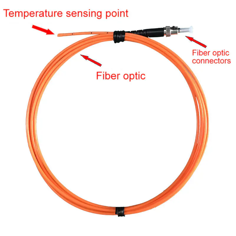
Standard Fluorescent Fiber Optic Temperature Probe
A general-purpose option when extended thermal construction is not required.
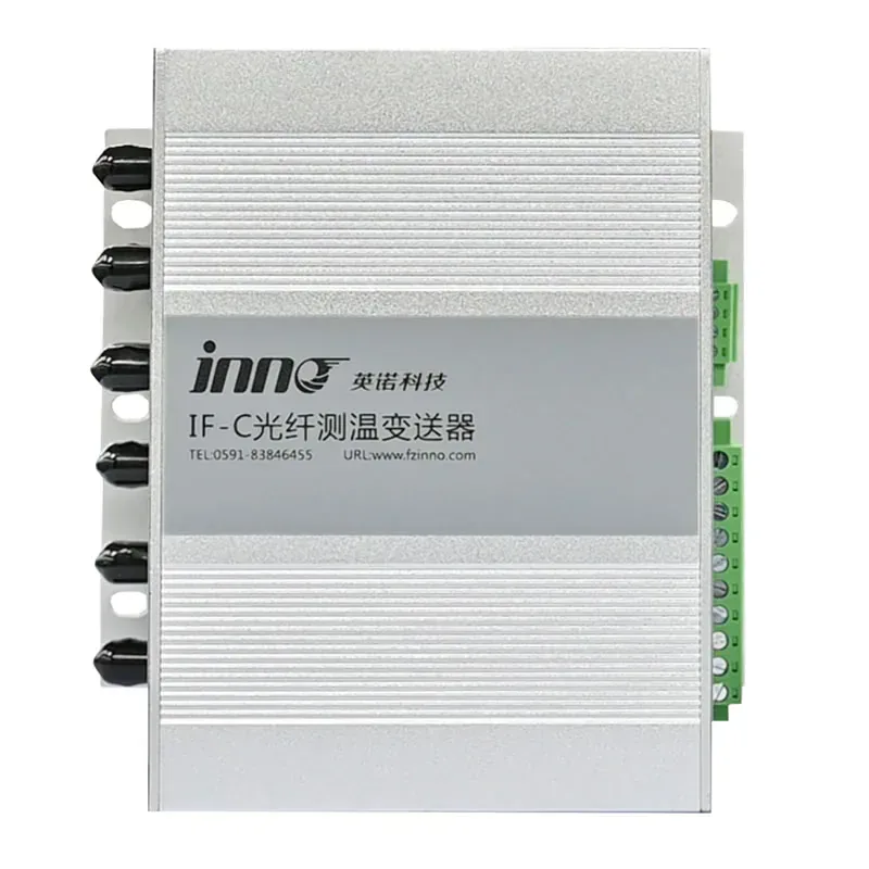
Multi-Channel Fiber Optic Temperature Transmitter
Centralizes several thermal test or process measurement points.
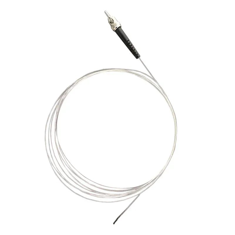
MRI & RF Fiber Optic Temperature Probe
A compact option for a different strong-field measurement scenario.
BUYER QUESTIONS
Frequently Asked Questions
What is the maximum temperature of every probe configuration?
There is no single universal maximum for every construction. The collected standard range is -40 °C to +260 °C, with higher configurations subject to review.
Does the whole fiber measure temperature?
No. Temperature is measured at the fluorescent sensing tip, not continuously along the full fiber.
Can the sheath material be selected?
The collected data lists a PTFE/Teflon sheath option. Final material and temperature compatibility must be confirmed.
Does the probe include a display or output?
No. The compatible instrument provides temperature calculation, display and communication outputs.
What details are required for selection?
Provide normal and excursion temperatures, target point, exposure time, medium, available space, sheath requirement, fiber route and instrument.
Can it be used in high-voltage tests?
The passive optical path is useful for many electrically demanding tests, subject to complete setup and insulation review.
PROBE SELECTION SUPPORT
Configure a Probe for the Required Temperature Range
Share normal and excursion temperatures, exposure time, target material, probe geometry, sheath requirement, fiber route and instrument location.
- Measurement location
- Required temperature range
- Fiber route and length
Need Help Selecting the Correct Probe Construction?
Share the measurement point, environment and installation constraints with INNO.