
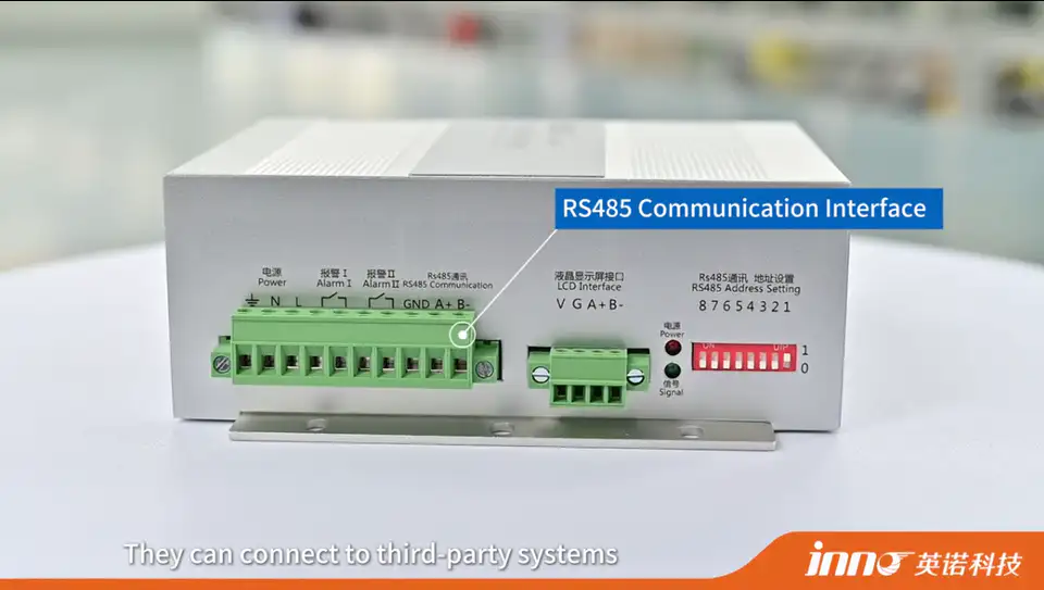
Fiber optic temperature monitoring systems can connect to PLC, SCADA and third-party platforms through the communication and output interfaces provided by the monitoring instrument or temperature transmitter. Depending on the selected model, these interfaces may include RS485, Modbus RTU, 4-20 mA, CAN, alarm relay outputs or Ethernet / TCP/IP.
The fiber optic probe itself does not normally communicate directly with a PLC. It sends an optical temperature-related signal to the monitoring instrument, which converts the signal into temperature data and then provides the required industrial output. This guide focuses on fluorescence-based point fiber optic temperature sensing, where the probe provides the optical measurement and the monitoring instrument handles data conversion and communication.
This separation between sensing and communication makes it possible to integrate fiber optic temperature measurement into existing control, monitoring and data-acquisition systems.
Key Takeaways
- Fiber optic probes normally connect first to a temperature monitoring instrument or transmitter.
- PLC and SCADA integration occurs through the monitoring instrument's communication or analog outputs.
- RS485 is a common industrial serial interface, while Modbus RTU is a common protocol used over it.
- 4-20 mA can be useful when an existing analog input system is already available.
- CAN or TCP/IP may be available depending on the monitoring instrument.
- Multi-channel systems can transmit temperature data from multiple independent sensing points.
How Does Fiber Optic Temperature Data Reach a PLC or SCADA System?
The data path generally follows this sequence: the fiber optic probe measures a selected physical temperature point, the optical signal travels through the fiber, the temperature monitoring instrument converts the optical response into temperature data, the instrument outputs digital, analog or relay signals, and a PLC, SCADA or third-party platform receives and processes that data.
In short: probe, then fiber, then monitoring instrument, then interface, then PLC or SCADA. System integration happens after the optical signal has already been converted into usable temperature data.
Does the Fiber Optic Temperature Probe Connect Directly to a PLC?
Normally, no. The probe produces an optical temperature-related signal rather than a conventional PLC electrical input, so a temperature transmitter, monitoring instrument or demodulator is needed to convert that signal into digital communication, an analog signal or a relay output.
The fiber optic probe itself does not provide RS485 or any other communication protocol directly - that capability belongs to the monitoring instrument.
What Interfaces Can a Fiber Optic Temperature Monitoring System Provide?
| Interface / Protocol | Signal Type | Typical Use | Main Consideration |
|---|---|---|---|
| RS485 | Digital serial | PLC / industrial controller | Requires protocol agreement |
| Modbus RTU | Communication protocol, commonly over RS485 | PLC / SCADA / HMI | Register mapping and communication settings |
| 4-20 mA | Analog | Existing analog input modules | Number of outputs and scaling |
| CAN | Digital bus | Embedded / equipment-level integration | Device compatibility |
| Ethernet / TCP/IP | Network communication | Host computer / remote monitoring / system platform | Depends on model and protocol |
| Alarm Relay | Discrete output | Alarm / interlock indication | Provides status, not full temperature data |
Available interfaces depend on the selected monitoring instrument. Not every model supports every interface.
How Does RS485 Integration Work?
RS485 is a physical serial communication interface commonly used in industrial environments. A fiber optic temperature monitoring instrument can use RS485 to send temperature data to a PLC, HMI, industrial computer or data acquisition unit.
Before integration, confirm the baud rate, device address, communication format, protocol, and channel mapping between the monitoring instrument and the receiving system.
How Is Modbus RTU Used for Fiber Optic Temperature Monitoring?
Modbus RTU commonly operates over RS485. Depending on implementation, the monitoring instrument can provide channel temperature values, alarm status and device status, which a PLC or SCADA system can poll to read temperature data, display trends or trigger logic.
Specific register addresses and function codes should be confirmed from the actual product documentation for the selected monitoring instrument rather than assumed.
When Is 4-20 mA a Practical Choice?
4-20 mA is a practical choice for existing analog PLC inputs, simple retrofits, one or several selected temperature values, and legacy control systems. It is a widely supported industrial signal that allows simple controller integration.
4-20 mA output configuration depends on the monitoring instrument - some models may provide one or more analog outputs depending on configuration, rather than every channel automatically having an independent analog output.
When Is CAN Used?
CAN may be used for embedded equipment, machine-level communication, OEM integration and controller networks. CAN support depends on the product model and project requirements, and specific protocol variants should be confirmed against the actual product rather than assumed.
Can Fiber Optic Temperature Monitoring Use Ethernet or TCP/IP?
Yes, where the selected monitoring instrument provides Ethernet or TCP/IP communication. This can support connections to a host computer, an industrial network, remote monitoring, a data server, or a third-party software platform.
TCP/IP is a network communication framework, not automatically equivalent to cloud monitoring. Cloud integration may require a gateway, software, a server, an API or an upper-level platform depending on the overall system architecture.
How Does Fiber Optic Temperature Monitoring Connect to a PLC?
A typical process includes confirming the PLC's available inputs or communication ports, confirming the monitoring instrument's output, selecting a supported interface and protocol combination such as RS485 with Modbus RTU, 4-20 mA, CAN or another available method, configuring communication parameters, mapping temperature channels, verifying engineering units, testing live temperature values, and configuring alarm or control logic if required.
This article does not provide brand-specific PLC programming, since the required steps vary by PLC platform and project.
How Does Fiber Optic Temperature Monitoring Connect to SCADA?
SCADA normally receives data through a PLC, an RTU, a gateway or an industrial communication interface rather than connecting directly to the sensing hardware. A typical path is fiber optic monitoring instrument to PLC or RTU to SCADA, or monitoring instrument to gateway or network to SCADA, depending on system architecture.
SCADA can then be used for real-time display, trend recording, alarm display, historical data and a multi-channel overview, without necessarily providing automatic control of every connected device.
Can the System Connect to Third-Party Monitoring Platforms?
Yes, if a compatible communication interface or data protocol is available. Third-party platforms can include industrial monitoring software, data acquisition systems, laboratory monitoring systems, host computer software, remote monitoring platforms, equipment controllers and customer-developed systems.
Compatibility depends on the interface, protocol, data format and software architecture of the third-party system.
Can Fiber Optic Temperature Monitoring Be Used with Laboratory Data Acquisition Systems?
Laboratory and test systems may need direct digital communication, multiple channels, centralized data collection, host computer connection and independent logging. Interfaces such as RS485, Modbus, CAN, TCP/IP or analog outputs may be available depending on the instrument.
This applies to environments such as high-voltage testing, RF and microwave testing, power electronics testing and material testing, where multiple channels often need to be logged together.
Can Temperature Data Be Sent to a Remote Monitoring Platform?
Yes, depending on the monitoring architecture. The monitoring instrument itself may support Ethernet or TCP/IP directly, or it may first connect to a PLC, gateway or industrial PC that then uploads data to a remote server or monitoring platform.
Not every model supports direct cloud connectivity. Remote integration should be planned around the actual instrument interface, gateway, software and network architecture.
How Are Multiple Temperature Channels Integrated?
One fiber optic point probe normally corresponds to one measurement channel. A multi-channel monitoring instrument can read several probes, assign each to a channel, output multiple values digitally, and send data to a PLC or SCADA system.
Special systems may support approximately 1-64 channels depending on the instrument and project requirements, though this range is not standard across every model.
Digital Communication vs Analog Output
| Integration Method | Best For | Advantages | Main Consideration |
|---|---|---|---|
| RS485 / Modbus | Multi-channel digital data | Multiple values over one communication link | Protocol configuration |
| 4-20 mA | Existing analog control systems | Simple integration | Each analog output represents one mapped value |
| CAN | Machine / embedded systems | Equipment-level communication | System compatibility |
| TCP/IP | Networked monitoring | Remote or host-system communication | Network architecture |
| Relay | Alarm state | Simple status indication | No continuous temperature value |
Which Interface Is Better for Multi-Channel Temperature Monitoring?
For multiple channels, digital communication is often more efficient because several temperature values can be transmitted through one communication link. Analog 4-20 mA can still be practical when the existing PLC infrastructure is analog, while relay outputs are only suitable for discrete alarm status.
The right choice depends on the number of channels, the existing controller, the required update method, the system architecture, and retrofit constraints.
Can Fiber Optic Temperature Monitoring Be Added to an Existing PLC or SCADA System?
Often yes, if the existing system has a compatible input or communication interface. Typical retrofit scenarios include an existing RS485 network, an available Modbus master, a spare analog input, gateway integration, or SCADA tag expansion.
Not every legacy system is guaranteed to be compatible - the existing architecture should be checked first.
What Information Is Needed for PLC or SCADA Integration?
- Number of temperature points
- Number of channels
- Monitoring instrument model
- Required communication interface
- PLC brand / controller type
- Available communication port
- SCADA architecture
- RS485 requirement
- Modbus requirement
- 4-20 mA requirement
- CAN requirement
- Ethernet / TCP/IP requirement
- Alarm relay requirement
- Required data update interval
- Instrument location
- Communication cable distance
- Existing gateway
- Remote monitoring requirement
What Should Be Confirmed Before System Integration?
Before integration, confirm the electrical interface, protocol, communication parameters, data format, channel quantity, temperature unit, scaling, alarm output, network topology, instrument power supply, system grounding, and PLC or SCADA input capacity.
Typical Integration Architectures
Architecture 1: Fiber Optic Probe to Temperature Monitoring Instrument to RS485 with Modbus RTU to PLC.
Architecture 2: Fiber Optic Probe to Monitoring Instrument to PLC to SCADA.
Architecture 3: Fiber Optic Probe to Temperature Transmitter to 4-20 mA to Existing PLC Analog Input.
Architecture 4: Fiber Optic Probe to Multi-Channel Monitor to Ethernet / Gateway to Third-Party Monitoring Platform.
The actual architecture depends on the instrument model and the customer's existing system.
Typical Applications for System Integration
| Application | Temperature Data Use | Typical Integration Direction |
|---|---|---|
| Transformer Monitoring | Winding / hot-spot temperature | PLC / SCADA |
| Switchgear Monitoring | Connection-point temperature | PLC / remote monitoring |
| Motor & Generator | Winding / stator temperature | PLC / machine monitoring |
| RF / Microwave Equipment | Internal process temperature | Host computer / controller |
| High-Voltage Testing | Test-point temperature | Laboratory DAQ / host PC |
| Power Electronics | Device / module test temperature | Test system / DAQ |
| Industrial Equipment | Process temperature | PLC / HMI / SCADA |
These are examples rather than a mandatory architecture for every project.
Does the Communication Interface Affect Temperature Measurement Accuracy?
Normally, the communication interface does not determine the underlying optical temperature measurement accuracy. Accuracy more directly depends on the probe, sensing element, monitoring instrument, system configuration, thermal contact and application conditions.
The communication interface mainly affects how data is transferred, though analog conversion can involve signal scaling and input resolution that should be accounted for in the system configuration.
Can Alarm Outputs Be Used Without PLC Communication?
Yes, where the monitoring instrument provides relay or alarm outputs. These can support an overtemperature alarm, a local warning, an interlock input or auxiliary control.
A relay output provides status information rather than complete temperature data, so it complements rather than replaces a full communication interface where continuous values are needed.
Common Fiber Optic Temperature System Integration Misunderstandings
The fiber optic probe connects directly to the PLC. Normally the probe connects to the monitoring instrument first, which then provides the PLC-compatible output.
RS485 and Modbus are the same thing. RS485 is a physical communication interface; Modbus RTU is a communication protocol commonly carried over RS485.
Every monitoring instrument supports every interface. Available interfaces depend on the specific model and configuration.
Every temperature channel automatically has an independent 4-20 mA output. This depends on instrument design and the selected configuration.
TCP/IP automatically means cloud monitoring. A network interface may support higher-level integration, but cloud connectivity depends on gateways, software and system architecture.
SCADA connects directly to the fiber optic probe. SCADA normally receives processed temperature data through the monitoring instrument, PLC, RTU, gateway or network layer.