
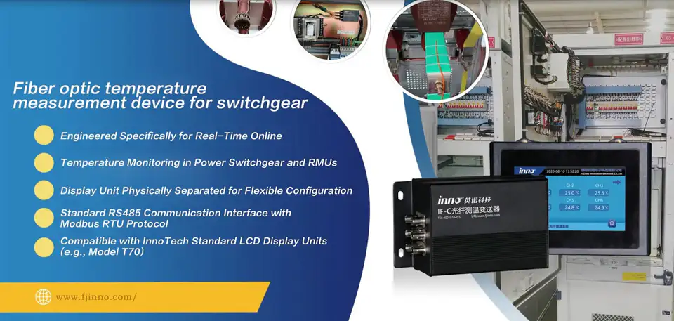
Switchgear temperature monitoring works by placing point temperature sensors at selected current-carrying locations, such as busbar joints, breaker connections and cable terminations, rather than measuring the cabinet as a whole. This guide covers which points to monitor, which switchgear temperature sensor methods are available, how many channels a configuration needs and how to send the data to PLC or SCADA.
- Switchgear temperature monitoring should focus on selected current-carrying points such as busbar joints, breaker connections and cable terminations.
- One point temperature sensor normally measures one defined physical location.
- Multi-point monitoring is needed when several phases, joints or cable terminations must be monitored independently.
- Common methods include infrared inspection, contact temperature sensors, wireless sensors and fiber optic temperature sensors, depending on the equipment and monitoring objective.
- Fiber optic sensors are especially useful where electrical isolation and immunity to electromagnetic interference are important.
- Temperature data can be sent to PLC, SCADA or other monitoring platforms through a compatible monitoring instrument.
Switchgear Temperature Monitoring Guide
- Switchgear Temperature Monitoring Points
- Busbar Temperature Monitoring
- Electrical Joint Temperature Monitoring
- Cable Termination Temperature Monitoring
- Switchgear Temperature Sensor Methods
- Fiber Optic Temperature Sensors for Switchgear
- Fiber Optic vs Wireless vs Infrared Monitoring
- Multi-Point Switchgear Temperature Monitoring
- Switchgear Temperature Sensor Channel Count
- PLC and SCADA Integration
- Switchgear Temperature Monitoring Selection Guide
- INNO Switchgear Temperature Monitoring
- Switchgear Temperature Monitoring FAQ
Where Should Temperature Be Monitored in Switchgear?
Typical monitoring points in medium-voltage and high-voltage switchgear include:
- Busbar joints
- Phase connections
- Breaker connection points
- Cable terminations
- Cable lugs
- Disconnect contacts where applicable
- Other selected current-carrying joints
Sensor positions are selected from the switchgear design and current path. Not every switchgear uses the same positions. The measurement point should correspond to the electrical connection or conductor location the engineer wants to monitor.
How Does Busbar Temperature Monitoring Work?
Busbar temperature monitoring normally measures selected points on phase busbars, busbar joints, branch connections and connection interfaces. Each busbar temperature sensor is installed at a chosen location and reports the temperature there.
A point sensor measures only its installed location. One sensor does not monitor a whole busbar. If A / B / C phases or several joints must be monitored, each needs its own sensing point.
Why Monitor Electrical Joint Temperature in Switchgear?
Localized heating in switchgear often occurs at current-carrying connection points, where electrical losses and heat dissipation conditions differ from the surrounding structure. Factors include current level, connection resistance, contact condition, joint design, conductor geometry, cooling / ventilation, surrounding temperature and equipment loading.
The goal of electrical joint temperature monitoring is to track temperature at selected joints over time, not to diagnose a cause automatically. A temperature rise does not by itself identify its cause, and alarm settings should follow the project specification. Connection-point temperature is one input to broader switchgear condition monitoring, and this guide covers measurement only.
How Is Cable Termination Temperature Monitored in Switchgear?
Cable termination temperature monitoring uses a sensing point at the cable lug, termination connection, conductor connection point or selected phase termination, depending on switchgear design. The reading is a local measurement, not the temperature of the whole cable.
If A / B / C terminations are monitored separately, that normally means three independent sensing points. Incoming and outgoing circuits, or several cable circuits, increase the number of points accordingly.
What Switchgear Temperature Sensor Methods Are Available?
| Method | What It Measures | Continuous Monitoring | Main Consideration |
|---|---|---|---|
| Infrared Inspection | Accessible surface temperature | Usually periodic unless a fixed thermal imaging system is used | Requires optical access / line of sight |
| Contact Electrical Sensor | Temperature at installed point | Yes | Electrical installation and insulation design |
| Wireless Temperature Sensor | Temperature at installed point | Usually, depending on sensor and power architecture | Power, communication and installation architecture depend on sensor design |
| Fiber Optic Temperature Sensor | Temperature at optical probe location | Yes | Requires optical monitoring instrument |
| Cabinet Air Sensor | Internal air temperature | Yes | Does not directly represent electrical joint temperature |
When Should a Fiber Optic Temperature Sensor Be Used in Switchgear?
A fiber optic switchgear temperature sensor is especially relevant when direct point measurement, electrical isolation and EMI immunity are important. Typical cases include:
- Medium-voltage switchgear
- High-voltage equipment
- Busbars
- Selected energized connection points
- Strong EMI environments
- Applications requiring electrical isolation
- Multi-point direct temperature measurement
The optical sensing path is electrically isolated and has high immunity to EMI. The monitoring instrument and external communication wiring remain electronic components, and proper switchgear design still applies. Not every switchgear needs fiber optic sensors.
Fiber Optic vs Wireless vs Infrared Switchgear Temperature Monitoring
| Feature | Fiber Optic Sensor | Wireless Contact Sensor | Infrared |
|---|---|---|---|
| Measurement | Direct installed point | Direct installed point | Accessible surface |
| Continuous Monitoring | Yes | Yes | Depends on system |
| Electrical Path at Sensing Point | Electrically isolated optical sensing path | Depends on sensor design | Non-contact |
| EMI Consideration | High immunity along optical path | Depends on design | Non-contact optical measurement |
| Requires Line of Sight | No | No | Yes for IR measurement |
| Multi-Point Monitoring | Yes | Yes | Possible depending on system |
| Typical Fit | Electrical isolation / strong EMI / selected point monitoring | Retrofit / wireless architecture where suitable | Inspection / accessible surfaces |
Different methods fit different monitoring architectures, and some projects combine them.
How Does Multi-Point Switchgear Temperature Monitoring Work?
One point fiber optic probe normally corresponds to one active measurement channel. Three phases at one location (A / B / C) normally means 3 measurement points. Two three-phase locations, such as a busbar joint plus a cable termination, may mean 6 measurement points. More monitored three-phase locations can lead to 9 / 12 channels or other project-specific channel counts.
Multi-point temperature monitoring of this kind reads each point independently through one multi-channel instrument. For INNO, switchgear and box-type substation projects commonly use 3 / 6 / 9 / 12 channel configurations. These are practical configuration patterns, not mandatory industry standards. The final number depends on the actual sensing points.
How Many Temperature Sensors Does a Switchgear Cabinet Need?
| Example Monitoring Scope | Example Point Count | Possible Channel Requirement |
|---|---|---|
| One three-phase connection | 3 points | 3 channels |
| Busbar joint + cable termination, three phases | 6 points | 6 channels |
| Three three-phase locations | 9 points | 9 channels |
| Four three-phase locations | 12 points | 12 channels |
This is only a configuration example. Actual channel count should follow the switchgear circuit design, the number of phases, the number of monitored connections and the project monitoring objective.
How Can Switchgear Temperature Monitoring Connect to PLC or SCADA?
A fiber optic probe does not normally connect directly to a PLC. The structure is:
Fiber Optic Probe → Multi-Channel Temperature Monitoring Instrument → PLC / SCADA / Remote Monitoring System
Possible integration options include:
- RS485 with a supported protocol such as Modbus RTU
- 4-20 mA
- Alarm relay
- CAN where supported
- Ethernet / TCP/IP where supported
Available interfaces depend on the instrument and configuration. PLC or SCADA can then handle channel temperature display, trend recording, alarm status, historical data and system-level monitoring.
Does Cabinet Air Temperature Represent Busbar or Joint Temperature?
No, not directly. Cabinet air temperature reflects the local enclosure environment, while busbar, joint and cable termination temperatures represent specific current-carrying locations.
Electrical cabinet temperature monitoring by air or ambient sensors cannot replace direct connection-point measurement. It can still provide useful context for interpreting connection-point readings.
How to Choose a Switchgear Temperature Monitoring Method
| Requirement | What to Consider |
|---|---|
| Measurement target | Busbar / joint / cable termination / cabinet air |
| Continuous or periodic monitoring | Online sensor vs infrared inspection |
| Electrical environment | Voltage level / insulation / EMI |
| Number of measurement points | Single point vs multi-point |
| New equipment or retrofit | Installation access and structure |
| Signal architecture | Local alarm / PLC / SCADA / remote platform |
| Sensor wiring | Electrical / wireless / optical |
| Channel quantity | 3 / 6 / 9 / 12 or project-specific |
| Monitoring instrument location | Inside cabinet / panel / external monitoring area |
Switchgear Temperature Sensors for New Equipment vs Retrofit Projects
New switchgear: temperature sensing points and fiber routing can be planned during cabinet design and assembly, together with the equipment layout.
Retrofit: existing clearances, access, mounting positions and communication architecture should be reviewed first. Sensor placement should follow the switchgear design and project engineering requirements.
INNO Fiber Optic Temperature Monitoring for Switchgear
INNO provides fluorescence-based point fiber optic temperature sensors and multi-channel monitoring instruments for switchgear, busbar, electrical joint and cable termination temperature monitoring. The fluorescent fiber optic temperature sensing technology page explains the sensing principle.
- Direct point temperature measurement
- Electrically isolated optical sensing path
- High EMI immunity along the optical sensing path
- Compact point probes
- Custom fiber length
- 3 / 6 / 9 / 12-channel configurations for common switchgear projects
- Other channel quantities available depending on instrument and project
- PLC / SCADA integration through compatible monitoring instruments
- OEM / ODM options for switchgear manufacturers and system integrators
Typical INNO point-probe references include an approximately -40 to 260 °C temperature range, approximately ±0.5 to ±1 °C accuracy, response under 1 s, approximately 2-3 mm probe diameter and approximately 0-20 m fiber length, depending on the probe, instrument and project configuration.
What Information Is Needed for a Switchgear Temperature Monitoring Configuration?
- Switchgear type
- Voltage level
- Number of cabinets
- Number of phases
- Measurement points
- Busbar joint locations
- Cable termination locations
- Number of required sensing points
- Required channels
- Fiber routing distance
- Monitoring instrument location
- Local display requirement
- PLC / SCADA requirement
- Communication interface
- Alarm output requirement