
Switchgear Fiber Optic Temperature Monitoring System
A configurable online fiber optic temperature monitoring system for switchgear busbar joints, contacts and cable terminations with local alarms and plant communication planning.
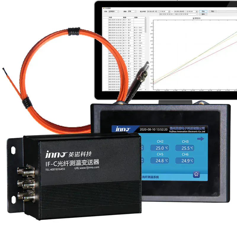
ONLINE SWITCHGEAR TEMPERATURE MONITORING SYSTEM
Keep direct temperature points available for local alarms and remote monitoring without using conductive sensor signal wiring at energized connections.
Use it when the project needs a complete switchgear-focused path from selected connection points to local status, alarms and plant data.
Choose a standalone multi-channel transmitter when the asset and probe plan are already defined; choose this system when probes, switchgear routing, channel mapping and outputs must be coordinated together.
- Selected busbar joints, breaker interfaces and cable terminations in switchgear compartments.
- Map every cubicle, phase and connection, select the matching probe attachment, protect the fiber route and configure the host channel and data plan.
One Switchgear Monitoring System From Point to Plant
This switchgear fiber optic temperature monitoring system coordinates passive fluorescent point probes, protected optical routes, compatible acquisition channels and the required local or supervisory outputs. It is intended for defined current-carrying interfaces rather than general cabinet-air measurement.
The monitoring arrangement can cover selected busbar joints, breaker or disconnect interfaces and cable terminations. Every channel should identify the lineup, cubicle, phase and connection so an alarm or trend can be traced to the correct physical point.
Continuous online use does not require a separate product page. Online data, alarms and communication are configuration functions of the same switchgear monitoring architecture and are now covered here.
POINT PLAN
Map Critical Connections Before Selecting Channels
Start with the current path and service workflow, then assign one sensing point to each connection that needs direct thermal visibility.
- Identify busbar joints, breaker interfaces and cable terminations by cubicle and phase.
- Keep corresponding phase locations mechanically consistent.
- Include only justified spare channels after the critical-point list is approved.
ONLINE MONITORING
Connect Local Alarms With Remote Data Review
The host and plant interface should preserve each point’s identity and define what happens when a threshold or signal fault is detected.
- Review local display, relay and alarm requirements.
- Confirm RS485 / Modbus mapping with the control-system team.
- Document tag names, update behavior and loss-of-signal handling during commissioning.
PRODUCT DATA
Technical Specifications
Select the final configuration around the equipment design and required measurement points.
APPLICATION FIT
Typical Project Uses
Explains the switchgear-specific online system as one configuration, avoiding separate pages for the same buyer intent.
Switchgear busbar joints
Review this product’s role, installation method and related components against the actual application.
Breaker and disconnect interfaces
Review this product’s role, installation method and related components against the actual application.
Cable terminations
Review this product’s role, installation method and related components against the actual application.
High-voltage distribution equipment
Review this product’s role, installation method and related components against the actual application.
BUYER QUESTIONS
Frequently Asked Questions
Is this different from an online switchgear temperature monitoring system?
No. Continuous online monitoring, alarms and remote communication are configuration functions of this retained switchgear system page, so a second overlapping product route is not needed.
Which switchgear points can be monitored?
Common candidates include reviewed busbar joints, breaker or disconnect interfaces and cable terminations. The final point list must follow the equipment design and maintenance objective.
Does one probe monitor an entire cubicle?
No. A fluorescent probe measures one defined point. Channel quantity follows the number of approved connections and any justified reference points.
Can the system send data to SCADA?
Compatible host configurations can be planned around RS485 / Modbus and alarm outputs. Confirm the final protocol, map and failure behavior for the project.
How should channels be named?
Use a consistent lineup, cubicle, phase and connection naming structure so every value and alarm maps to one physical location.
What should be reviewed before installation?
Review electrical clearances, probe attachment, moving mechanisms, compartment crossings, connector access, host placement and the plant-data interface.
RELATED PRODUCTS
Related Components and Systems
These products serve different roles in the same optical temperature-measurement path.
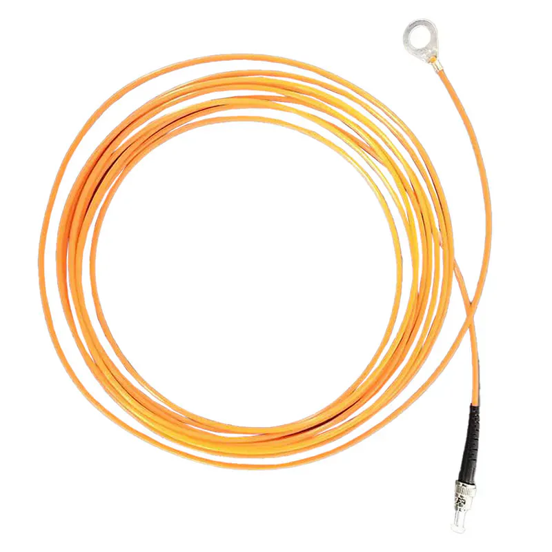
Busbar & Bolt Connection Fiber Optic Temperature Probe
An O-ring style fluorescent probe designed for direct point temperature measurement beneath busbar bolts and electrical connection fasteners.
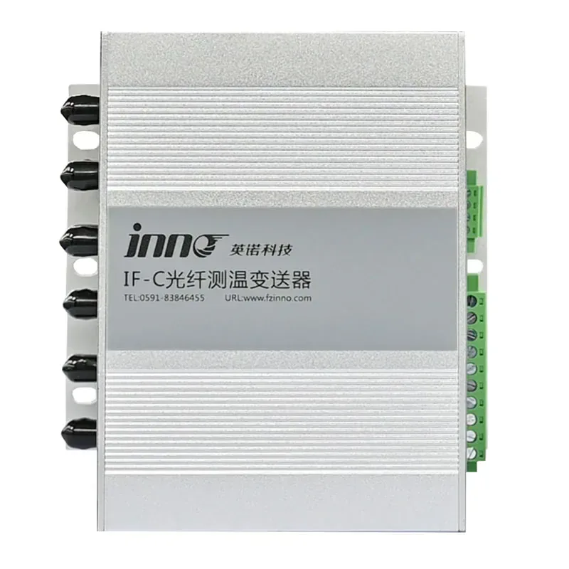
IF-C Multi-Channel Fiber Optic Temperature Transmitter
A configurable multi-channel host that converts signals from separate fluorescence fiber optic probes into temperature data, relay alarms, RS485 communication, and optional analog outputs.
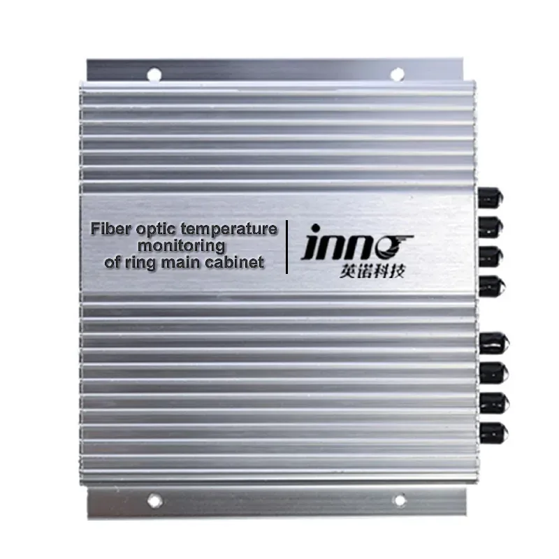
Ring Main Unit Cable Joint Fiber Optic Temperature Monitoring System
A configured point-temperature monitoring system for reviewed cable-joint and connection hot spots in ring main units.
PRODUCT CONFIGURATION REVIEW
Plan the Right Product Configuration
Tell us how this switchgear fiber optic temperature monitoring system will be used. INNO can review the measurement point, installation route, channel requirements and system interface against the selected product.
- Measurement target: Selected busbar joints, breaker interfaces and cable terminations in switchgear compartments.
- Installation method: Map every cubicle, phase and connection, select the matching probe attachment, protect the fiber route and configure the host channel and data plan.
- Product selection: Switchgear lineup and critical current-carrying points
- System requirement: RS485 / Modbus and plant-data requirements
Include the operating temperature range, number of measurement points and required communication or alarm outputs where applicable.