
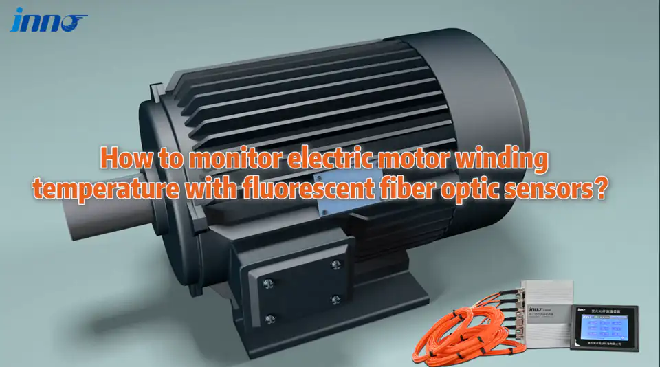
Motor winding temperature is measured with a motor winding temperature sensor installed at selected stator winding locations, or estimated indirectly from winding resistance. Surface measurements can provide complementary thermal information, but they do not directly represent internal winding temperature. Each method captures a different thermal quantity. This guide compares PT100 / RTD, thermistor, thermocouple, fiber optic, resistance and infrared methods, and shows where each one fits.
- Motor winding temperature is usually measured with sensors installed at selected stator winding locations.
- PT100 / RTD sensors are widely used for conventional electric motor winding temperature monitoring.
- Fiber optic temperature sensors provide direct point measurement with an electrically isolated optical sensing path.
- Thermocouples and thermistors may also be used depending on motor design and monitoring requirements.
- Winding resistance can be used to determine average winding temperature, especially during testing, but it does not provide a live internal hot-spot reading.
- Housing or infrared surface temperature does not directly represent the internal stator winding temperature.
Motor Winding Temperature Measurement Guide
- Motor Winding Temperature Measurement Methods
- Electric Motor Temperature Sensor Types
- Stator Temperature Sensor Placement
- Fiber Optic Motor Winding Temperature Sensors
- Motor Temperature Sensor Comparison
- Multi-Point Motor Winding Temperature Monitoring
- PLC and Motor Temperature Monitoring
- Motor Winding Temperature Sensor Selection
- INNO Fiber Optic Motor Temperature Monitoring
- Motor Winding Temperature Sensor FAQ
How Is Motor Winding Temperature Measured?
Motor winding temperature can be measured through direct sensing or indirect temperature estimation. The table shows what each method actually reports.
| Measurement Method | What It Measures | Direct or Indirect | Typical Use |
|---|---|---|---|
| PT100 / RTD | Temperature at installed winding location | Direct point measurement | Industrial motors |
| Thermistor | Temperature response / threshold at installed location | Local temperature response / threshold sensing | Motor protection / temperature monitoring |
| Thermocouple | Temperature at installed location | Direct point measurement | Testing / suitable motor designs |
| Fiber Optic Temperature Sensor | Temperature at optical probe location | Direct point measurement | High-voltage / EMI-sensitive motor environments |
| Winding Resistance | Average winding temperature derived from resistance change | Indirect / calculated average | Motor testing |
| Infrared | Accessible surface temperature | Direct surface measurement, not internal winding measurement | Inspection / accessible surfaces |
These methods do not measure exactly the same thermal quantity. A point sensor reports one location, a resistance calculation reports an average, and infrared reports a surface. Compare them on that basis, not on a single temperature number.
What Electric Motor Temperature Sensors Are Commonly Used?
PT100 / RTD Motor Winding Temperature Sensors
PT100 / RTD sensors are widely used in industrial motor winding temperature monitoring. They can be embedded at selected winding locations, measure temperature through electrical resistance, and integrate with suitable RTD input modules, transmitters or protection hardware.
Thermistors for Electric Motor Protection
Thermistors are commonly used for motor temperature protection and threshold detection, depending on the motor design. Their role may be protection-oriented rather than precise continuous temperature indication.
Thermocouples for Motor Temperature Measurement
Thermocouples suit certain testing, development and industrial measurement tasks. They give direct point measurement where the motor design and installation allow.
Fiber Optic Motor Winding Temperature Sensors
A fiber optic sensor measures temperature through an optical probe and optical fiber rather than conductive temperature-measurement leads at the sensing point. It reports the temperature at the probe location and is discussed in more detail below.
Where Is a Stator Temperature Sensor Installed?
For winding monitoring, a stator temperature sensor is normally placed at selected stator winding locations based on motor design. Depending on construction, these may include:
- Winding slots
- Coil sections
- Winding end regions
- Predicted higher-temperature locations
The hottest location is not identical in every motor. Sensor placement depends on winding design, motor size, cooling, the insulation system, expected thermal distribution and the manufacturer's design. There is no fixed standard position that applies to all motors.
A well-placed winding sensor represents the location where it sits, so the placement decision matters as much as the sensor type. Similar measurement principles can apply to generator stator windings, but generator monitoring should be selected according to the generator design.
When Should a Fiber Optic Temperature Sensor Be Used in an Electric Motor?
Not every motor needs fiber optic sensing. It is especially relevant when direct point measurement, electrical isolation and EMI immunity are important, for example in:
- High-voltage motors
- Strong electromagnetic fields
- VFD / inverter-driven systems where EMI or electrical isolation is a measurement concern
- Test motors
- Applications requiring electrical isolation
- Applications requiring direct multi-point winding measurement
- Locations where conductive sensing leads are undesirable
The optical sensing path is electrically isolated and has high immunity to EMI. The monitoring instrument and external communication wiring remain electronic components, so normal installation practice still applies.
PT100 vs Thermocouple vs Fiber Optic Motor Winding Temperature Sensor
| Feature | PT100 / RTD | Thermocouple | Fiber Optic Temperature Sensor |
|---|---|---|---|
| Measurement Signal | Electrical resistance | Thermoelectric voltage | Optical |
| Direct Point Measurement | Yes | Yes | Yes |
| Conductive Measurement Leads | Yes | Yes | No along optical sensing path |
| EMI Consideration | Depends on wiring / installation | Depends on wiring / installation | High immunity along optical path |
| Electrical Isolation at Probe | Requires system design | Requires system design | Electrical isolation through the optical sensing path |
| Multi-Point Monitoring | Yes, with suitable acquisition system | Yes, with suitable acquisition system | Yes, with multi-channel optical instrument |
| Typical Application | Conventional industrial motors | Testing / industrial applications | High-voltage / EMI / electrically isolated measurement |
All three give direct point measurement. The main difference is the signal path and how the installation handles the electrical environment, not a general ranking.
Does Motor Housing Temperature Show Motor Winding Temperature?
Not directly. Motor frame or housing temperature reflects overall heat transfer but does not equal internal winding temperature. Bearing temperature is a separate thermal condition and is monitored separately.
Infrared inspection of the external housing cannot directly replace an embedded stator temperature sensor. Surface temperature is still useful for inspection, comparison, thermal trends and monitoring of accessible components.
Can Motor Winding Resistance Be Used to Measure Temperature?
Yes. Winding resistance can be used to calculate an average winding temperature, because conductor resistance changes with temperature. It is commonly used in testing and temperature-rise evaluation.
The result is an average. It does not identify individual hot spots, and it is not equivalent to continuous embedded point monitoring.
How Does Multi-Point Motor Winding Temperature Monitoring Work?
One fiber optic point probe normally corresponds to one active measurement channel. Multiple probes can measure different stator locations, different phases, different winding sections or selected hot-spot candidate locations. The probes measure only where they are installed and do not automatically identify the hottest point.
There is no fixed standard channel count for motors. With INNO, channel quantity can be configured according to the number of required sensing points, with customized multi-channel systems available depending on the monitoring instrument and project. Special systems may be configurable from approximately 1 to 64 channels, although not every instrument supports every channel count.
How Can Motor Winding Temperature Sensors Connect to PLC or Monitoring Systems?
PT100 / RTD sensors may connect through an RTD input module, a temperature transmitter or a monitoring relay, depending on the architecture.
A fiber optic probe does not normally connect directly to a PLC. The link is:
Fiber Optic Probe → Temperature Monitoring Instrument → PLC / SCADA / DAQ
INNO monitoring instrument integration options may include:
- RS485 with a supported protocol such as Modbus RTU
- 4-20 mA
- Alarm relay
- CAN where supported
- Ethernet / TCP/IP where supported
Available interfaces depend on the monitoring instrument and configuration.
How to Choose a Motor Winding Temperature Sensor
Do not select a sensor based only on temperature range. The measurement point, electrical environment, installation stage, number of points and integration method decide the fit.
| Requirement | What to Consider |
|---|---|
| Motor voltage level | Electrical isolation requirements |
| Measurement location | Internal winding / surface / bearing / housing |
| Direct or average measurement | Embedded sensor vs resistance method |
| EMI environment | Motor drive / VFD / electrical environment |
| Number of sensing points | Single-point vs multi-point monitoring |
| Sensor installation stage | New motor / manufacturing / retrofit |
| Temperature range | Expected winding operating range |
| Signal output | RTD / analog / digital communication |
| Monitoring system | Local protection / PLC / SCADA / DAQ |
Motor Winding Temperature Sensors for New Motors vs Retrofit Projects
New motors: embedded sensing is easiest to plan during motor manufacturing or winding assembly. For fiber optic sensing, selected probes can be positioned during manufacturing before winding and insulation assembly is completed, according to the motor design.
Existing motors: retrofitting an internal embedded sensor can be much more difficult. Depending on the existing structure, the practical options may be an existing RTD, an accessible measurement point, external surface measurement or the existing monitoring system.
INNO Fiber Optic Temperature Sensors for Motor Winding Monitoring
INNO provides fluorescence-based point fiber optic temperature sensors and multi-channel monitoring instruments for direct temperature measurement at selected motor winding locations. The fluorescent fiber optic temperature sensing technology page describes the sensing principle.
- Point temperature measurement at selected stator winding locations
- Electrically isolated optical sensing path
- High EMI immunity along the optical sensing path
- Compact probe options
- Custom fiber length
- Multi-channel monitoring
- PLC / SCADA / DAQ integration through compatible monitoring instruments
- OEM / ODM options for motor and equipment manufacturers
Typical references are approximately -40 to 260 °C temperature range, approximately ±0.5 to ±1 °C accuracy, response under 1 s, approximately 2-3 mm probe diameter and approximately 0-20 m fiber length, depending on probe, instrument and project configuration.
What Information Is Needed to Select a Motor Winding Temperature Sensor?
- Motor type
- Rated voltage
- Motor power / size
- Stator winding structure
- New motor or retrofit
- Measurement locations
- Number of sensing points
- Expected temperature range
- Probe size requirement
- Required fiber length
- Number of channels
- Monitoring instrument location
- PLC / SCADA / DAQ requirement
- Required communication interface