
Semiconductor & ESC Fiber Optic Temperature Monitoring System
Fiber optic temperature monitoring for semiconductor ESCs, etching and deposition equipment, with configurable channels and industrial outputs.
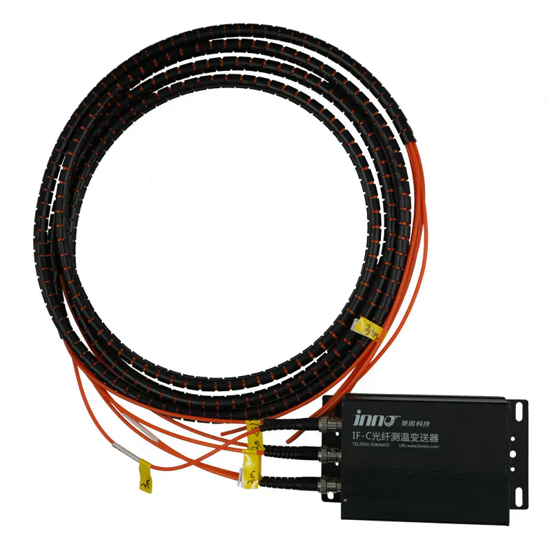
SEMICONDUCTOR AND ESC TEMPERATURE MONITORING SYSTEM
Optical Temperature Measurement for ESC and RF Equipment
Passive fluorescence probes provide temperature feedback at selected equipment points where RF fields and electromagnetic interference complicate electrical sensing.
The system brings together probes, optical signal processing and selected outputs. Probe mounting, channel count and equipment interfaces are configured for the application.
- Selected thermal points in an electrostatic chuck or semiconductor heating assembly.
- Coordinate sensing-tip placement in the ESC base, protected fiber routing and the instrument interface with the equipment designer.
Temperature Feedback for Semiconductor Equipment
This fluorescence fiber optic temperature monitoring system measures selected points in semiconductor heating and processing equipment. Applications include electrostatic chuck bases, etching and deposition equipment, and RF or induction heating assemblies.
The sensing tip uses temperature-dependent fluorescence and connects optically to the measurement instrument. The configuration supports 1–64 channels, a −40 °C to +240 °C range, 0.1 °C resolution and ±1 °C accuracy. Channel count, probe geometry and extended-range or enhanced-accuracy options are selected for the equipment.
A measurement period below one second supports temperature trend acquisition. Optical signal diagnostics help identify sensor faults, while RS485 / Modbus and configurable 4–20 mA output support the planned equipment interface. Measurement period describes acquisition timing; it is separate from the installed probe’s thermal response.
ESC INTEGRATION
Position the Probe Around the Thermal Process
An ESC installation begins with the target temperature point and the available sensing-tip location in the chuck base. The equipment designer defines the mounting arrangement and route to the external instrument.
- Identify the locations needed to characterize the heating process.
- Confirm probe diameter, fiber length and protected routing.
- Match optical channels and outputs to the equipment control architecture.
MONITORING AND DIAGNOSTICS
Track Temperature Trends and Sensor Status
Continuous point measurements support equipment monitoring and fault analysis. Optical signal diagnostics provide information about the sensing path alongside the temperature readings.
- Record changes at the selected ESC or heating points.
- Use sensor-status information when investigating abnormal readings.
- Configure Modbus data or analog outputs for the receiving equipment.
PRODUCT DATA
Technical Specifications
Select the final configuration around the equipment design and required measurement points.
APPLICATION FIT
Typical Project Uses
Select the sensing location and integration arrangement around the thermal question each channel needs to answer.
Electrostatic chuck temperature monitoring
Review this product’s role, installation method and related components against the actual application.
Semiconductor etching equipment
Review this product’s role, installation method and related components against the actual application.
Deposition equipment
Review this product’s role, installation method and related components against the actual application.
RF and induction heating equipment
Review this product’s role, installation method and related components against the actual application.
BUYER QUESTIONS
Frequently Asked Questions
Where is the probe installed for ESC measurement?
The sensing tip can be integrated at a selected location in the electrostatic chuck base. Position, mounting and protected optical routing are agreed with the equipment designer.
How many temperature points can the system monitor?
The system is configurable from 1 to 64 channels. The final quantity follows the approved measurement-point plan.
Which interfaces are available?
RS485 / Modbus communication and a configurable 4–20 mA analog output are available. Confirm the required output configuration with the equipment I/O plan.
Does a measurement period below one second mean the probe responds thermally in one second?
No. The measurement period describes the instrument’s acquisition cycle. Thermal response also depends on probe construction, mounting and contact with the measured part.
Can the system identify sensor faults?
Optical signal detection and diagnostic algorithms support sensor-fault identification. Confirm the required status reporting and integration for the selected instrument.
RELATED PRODUCTS
Related Components and Systems
These products serve different roles in the same optical temperature-measurement path.
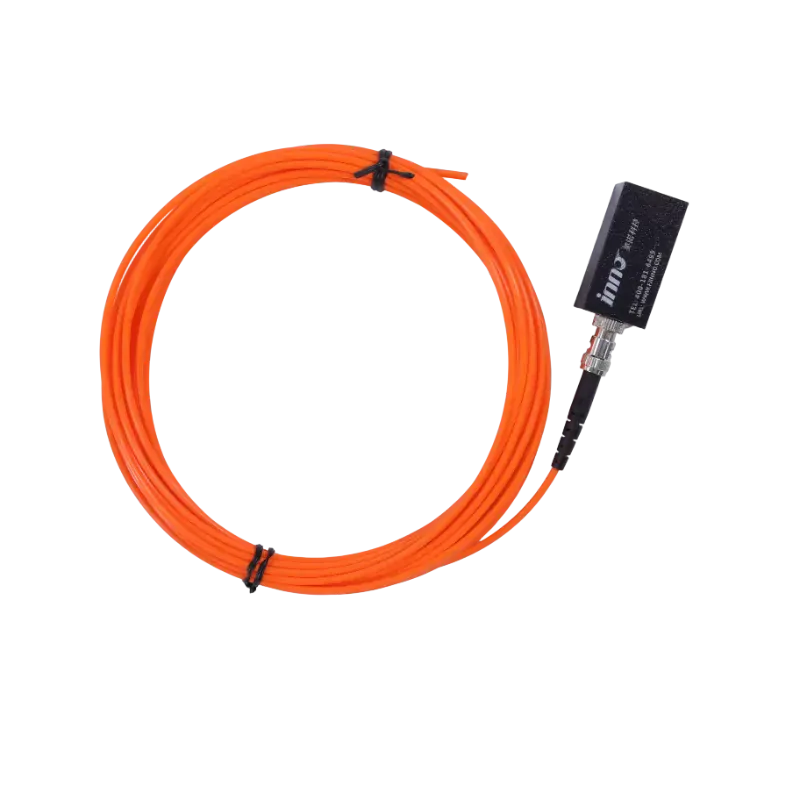
Custom OEM Fiber Optic Temperature Measurement Module
A custom optical temperature acquisition module development path for equipment makers with project-specific channels, interfaces and mechanical constraints.
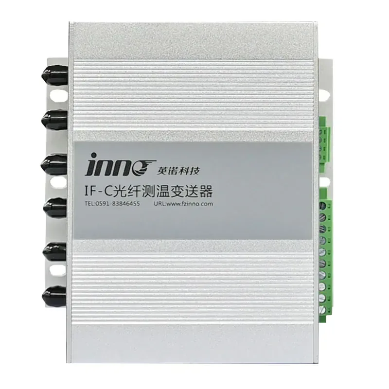
IF-C Multi-Channel Fiber Optic Temperature Transmitter
A configurable multi-channel host that converts signals from separate fluorescence fiber optic probes into temperature data, relay alarms, RS485 communication, and optional analog outputs.
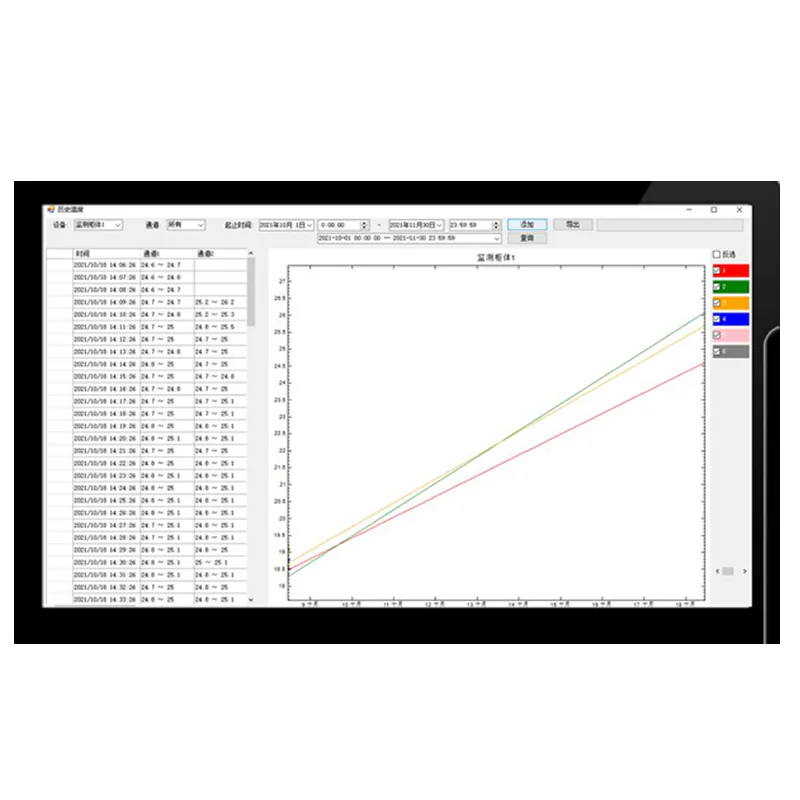
Fiber Optic Temperature Monitoring Software & Custom Cloud Platform
Monitor fiber optic temperature channels with local Modbus RTU software or a custom cloud platform for trends, historical data, device management and alarms.
PRODUCT CONFIGURATION REVIEW
Plan the Right Product Configuration
Tell us how this semiconductor fiber optic temperature monitoring will be used. INNO can review the measurement point, installation route, channel requirements and system interface against the selected product.
- Measurement target: Selected thermal points in an electrostatic chuck or semiconductor heating assembly.
- Installation method: Coordinate sensing-tip placement in the ESC base, protected fiber routing and the instrument interface with the equipment designer.
- Product selection: ESC or heating-zone measurement locations
- System requirement: Equipment communication and alarm requirements
Include the operating temperature range, number of measurement points and required communication or alarm outputs where applicable.