
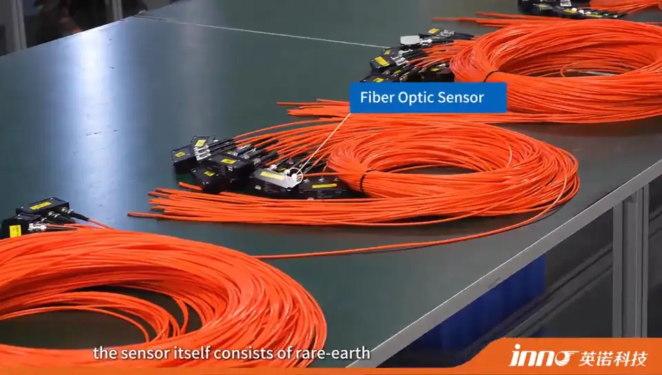
Choosing a fiber optic temperature monitoring system starts with the number of physical temperature points, not with the instrument model. Each independent point normally needs one probe and one active channel. After the sensing points are defined, the system can be selected around probe type, fiber length, temperature range, channel count, monitoring instrument, alarm requirements and communication interfaces for multi-channel temperature monitoring.
- Define the exact physical temperature points first.
- Count the number of independent sensing points.
- Match one point probe to one active measurement channel.
- Confirm the required temperature range and probe structure.
- Determine the required fiber length from the actual routing.
- Select a monitoring instrument with enough channels.
- Confirm local display, alarm and communication requirements.
- Check PLC, SCADA or DAQ integration before finalizing the system.
- Reserve spare channels only when the project requires future expansion.
Fiber Optic Temperature Monitoring System Selection Guide
- What Is Included in a Fiber Optic Temperature Monitoring System?
- How Many Temperature Points Need to Be Monitored?
- How Many Channels Does the Monitoring System Need?
- How to Choose the Fiber Optic Temperature Probe
- How to Choose the Required Fiber Length
- How to Choose the Fiber Optic Monitoring Instrument
- Which Outputs and Communication Interfaces Are Needed?
- How System Selection Changes by Application
- How to Connect the Monitoring System to PLC or SCADA
- Should You Reserve Spare Monitoring Channels?
- New Equipment vs Retrofit System Selection
- OEM Fiber Optic Temperature Monitoring Module
- Fiber Optic Temperature Monitoring System Checklist
- Configuration Examples
- Information Needed for System Selection
- INNO Fiber Optic Temperature Monitoring Systems
- Fiber Optic Temperature Monitoring System FAQ
What Is Included in a Fiber Optic Temperature Monitoring System?
A complete fiber optic temperature monitoring system generally includes the following components:
- Fiber optic temperature probe
- Optical fiber / extension assembly
- Feedthrough or connector arrangement where applicable
- Monitoring instrument / transmitter / demodulator
- Power supply as required
- Local display where supported
- Alarm output where required
- Communication interface
- PLC / SCADA / DAQ integration where required
The system link is: Fiber Optic Probe → Optical Fiber → Monitoring Instrument → Alarm / Display / Communication → PLC / SCADA / DAQ.
The probe and the monitoring instrument are different components. The probe senses temperature at the selected physical point, while the monitoring instrument interrogates the probe and converts the optical response into temperature data.
How Many Temperature Points Need to Be Monitored?
Selecting a fiber optic temperature monitoring system does not start with the channel number. It starts with the actual physical sensing points that need to be measured, such as selected winding positions in a transformer, busbar joints or cable terminations in switchgear, selected stator winding locations in a motor, or selected device-under-test (DUT) points on a test bench. One measurement point corresponds to one physical location.
| Monitoring Requirement | Example Independent Points |
|---|---|
| Three-phase connection | 3 points if each phase is measured separately |
| Two three-phase connections | 6 points |
| Three three-phase connections | 9 points |
| Four three-phase connections | 12 points |
| Transformer winding monitoring | Project-specific |
| Test bench | Depends on DUT and test points |
These are configuration examples, not industry standards.
How Many Channels Does a Fiber Optic Temperature Monitoring System Need?
For point sensing, the required active channels for multi-channel fiber optic temperature monitoring normally equal the number of independent temperature points measured simultaneously. Total channel capacity equals active channels plus any planned spare channels. Spare capacity depends on the future expansion plan for the project, not on a fixed rule.
Common INNO configuration patterns may include 1 / 2 / 3 / 4 channels for compact or OEM configurations, 3 / 6 / 9 / 12 / 16 channels for electrical equipment monitoring, and special configurations up to approximately 64 channels depending on system architecture. Not every instrument model supports every channel count. For more detail on matching channel count to project scope, see How Many Channels Do You Need for Fiber Optic Temperature Monitoring?
| Required Points | Minimum Active Channels | Possible System Approach |
|---|---|---|
| 1 | 1 | Single-channel or compact instrument |
| 3 | 3 | 3-channel or higher-capacity instrument |
| 6 | 6 | 6-channel or higher-capacity instrument |
| 9 | 9 | 9-channel or higher-capacity instrument |
| 12 | 12 | 12-channel or higher-capacity instrument |
| Custom | Match actual point count | Custom multi-channel configuration |
A higher-capacity instrument may be selected when future expansion is planned.
How to Choose the Fiber Optic Temperature Probe
For system selection, the probe factors that matter most are the required temperature range, probe diameter, sensing tip structure, installation space, electrical environment, mechanical mounting, fiber routing and application.
Typical INNO point-probe references include a temperature range of approximately -40 to 260 C, accuracy of approximately +/-0.5 to +/-1 C, response under 1 s, and a probe diameter of approximately 2-3 mm, depending on probe configuration. For a full walkthrough of probe selection, see How to Choose a Fiber Optic Temperature Sensor.
How to Choose the Required Fiber Length for a Fiber Optic Temperature Monitoring System
Fiber length should be based on actual routing rather than a fixed default. A practical way to estimate it is: required fiber length = internal routing + route to feedthrough + external routing + installation allowance.
A range of 3-5 m can be a practical initial reference for many equipment installations, and INNO probes are typically available with approximately 0-20 m of fiber depending on configuration. The final length should follow the actual project routing rather than a general assumption that longer or shorter is inherently better. See How to Choose the Right Fiber Length for a Fiber Optic Temperature Sensor for more detail.
How to Choose a Fiber Optic Temperature Monitoring Instrument
Instrument selection depends on several project-specific factors:
| Instrument Requirement | Selection Question |
|---|---|
| Channel count | How many independent probes must be read simultaneously? |
| Display | Is local temperature indication required? |
| Alarm | Does the project need relay outputs? |
| Analog output | Is 4-20 mA required? |
| Serial communication | Is RS485 required? |
| Protocol | Is Modbus RTU or another supported protocol required? |
| Network | Is Ethernet / TCP/IP required where available? |
| OEM integration | Is a compact module required instead of a finished monitor? |
Not every model supports every option listed above.
Which Outputs and Communication Interfaces Are Needed?
RS485 is a physical serial interface. Modbus RTU is a protocol commonly used over RS485. 4-20 mA is an analog signal. An alarm relay is a discrete alarm or status output. CAN is a bus interface where supported, and Ethernet / TCP/IP is a network option where supported. Different projects may use different outputs simultaneously, depending on the instrument selected.
How Does Fiber Optic Temperature Monitoring System Selection Change by Application?
| Application | Typical Sensing Target | Main System Selection Focus |
|---|---|---|
| Transformer | Selected winding / hot-spot candidate points | Embedded probes, fiber routing, multiple channels |
| Switchgear | Busbar joints / breaker connections / cable terminations | 3 / 6 / 9 / 12-point configurations depending on project |
| Motor | Selected stator winding locations | Probe size, installation, isolation, channel count |
| High-Voltage Test | DUT or selected energized component | Electrical isolation, fiber routing, DAQ integration |
| MRI / Magnetic Field | Selected measurement points | Optical path, material requirements, instrument location |
| Microwave / RF | Material or equipment points | Probe structure, routing, instrument outside active field where appropriate |
| Power Electronics | IGBT / SiC / selected test points | Compact probe, response, multi-channel test measurement |
Specific channel counts are not fixed by application; they follow the actual sensing plan. For related guidance, see How Is Motor Winding Temperature Measured? and How to Monitor Temperature in Switchgear Busbars, Joints and Cable Terminations.
How Can a Fiber Optic Temperature Monitoring System Connect to PLC or SCADA?
The integration path is: Fiber Optic Probe → Monitoring Instrument → Industrial Interface → PLC / SCADA / DAQ / Third-Party Platform. The probe itself does not normally communicate directly with PLC or SCADA.
Depending on the instrument, possible interfaces include RS485 with a supported protocol such as Modbus RTU, 4-20 mA, alarm relay, CAN where supported, and Ethernet / TCP/IP where supported. Some architectures may also require a gateway, controller or integration layer depending on the platform. For more detail, see How Can Fiber Optic Temperature Monitoring Systems Connect to PLC, SCADA and Third-Party Platforms?
Should You Reserve Spare Channels in a Fiber Optic Temperature Monitoring System?
Sometimes, but not automatically. Spare channels are useful when the project anticipates future additional sensing points, staged equipment expansion, expected changes in monitoring scope, or reserved capacity on an OEM platform. Spare capacity is less useful for a fixed test fixture, a fixed sensor count, a cost-sensitive compact OEM module, or equipment with no planned future monitoring expansion. There is no fixed percentage that applies to every project.
New Equipment vs Retrofit Fiber Optic Temperature Monitoring System Selection
For new equipment, sensing points can be planned during equipment design, probe routing can be planned in advance, channel count can be matched early, and the communication interface can be coordinated with the control system.
For a retrofit, existing access, mounting position, routing, feedthrough, available installation space and the existing PLC or SCADA interface need to be confirmed before the system is selected.
When Should You Choose an OEM Fiber Optic Temperature Monitoring Module?
An OEM fiber optic temperature monitoring module is often considered by equipment manufacturers, test equipment manufacturers, system integrators and custom controller manufacturers. Selection factors may include a 1-4 channel compact architecture, no local display if unnecessary, host system integration, the required communication interface, enclosure integration, custom connectors, custom fiber length and custom channel configuration. An OEM module should not be described as a complete monitoring system if it is only a development module.
Fiber Optic Temperature Monitoring System Selection Checklist
| Selection Item | Information to Confirm |
|---|---|
| Application | Transformer / switchgear / motor / test / MRI / microwave / other |
| Measurement points | Exact physical locations |
| Active channels | Number of simultaneously measured points |
| Spare channels | Future expansion requirement |
| Temperature range | Expected minimum and maximum |
| Probe size | Available installation space |
| Fiber length | Actual routing requirement |
| Monitoring instrument | Finished unit or OEM module |
| Local display | Required / not required |
| Alarm output | Relay requirement |
| Analog output | 4-20 mA requirement |
| Communication | RS485 / supported protocol / network |
| Integration | PLC / SCADA / DAQ / third-party platform |
| Documentation | Project-specific requirements |
Fiber Optic Temperature Monitoring System Configuration Examples
Example 1: Switchgear
Requirement: 6 independent busbar / connection points.
Possible configuration: 6 probes, 6 active channels, a monitoring instrument, and RS485 with a supported protocol such as Modbus RTU.
Example 2: Transformer
Requirement: 9 selected winding measurement points.
Possible configuration: 9 probes, a suitable 9-channel or higher-capacity monitoring instrument, the required fiber length, and a PLC / SCADA interface. Actual transformer probe locations follow the transformer design.
Example 3: Test Equipment OEM
Requirement: 4 independent points.
Possible configuration: 4 probes, a compact 4-channel OEM measurement module, and a host system communication interface.
These are configuration examples, not universal system designs.
INNO Fiber Optic Temperature Monitoring Systems
INNO provides fluorescence-based point fiber optic temperature probes, monitoring instruments and configurable multi-channel temperature monitoring solutions for electrical equipment, industrial equipment and test systems.
- Point fiber optic temperature probes
- Compact probe options
- Custom fiber length
- Multi-channel monitoring
- 1-4 channel OEM module configurations where applicable
- 3 / 6 / 9 / 12 / 16-channel equipment monitoring configurations depending on instrument
- Special multi-channel configurations depending on project architecture
- RS485 and supported communication protocols depending on instrument
- 4-20 mA and relay outputs where supported
- PLC / SCADA / DAQ integration
- OEM / ODM support
Typical INNO point-probe references may include a temperature range of approximately -40 to 260 C, accuracy of approximately +/-0.5 to +/-1 C, response under 1 s, probe diameter of approximately 2-3 mm, and fiber length of approximately 0-20 m. Channel count depends on the instrument and project configuration, and exact specifications depend on the selected probe, monitoring instrument and project.
What Information Should You Send When Requesting a Fiber Optic Temperature Monitoring System?
- Application
- Equipment type
- Voltage level where relevant
- Number of measurement points
- Location of each sensing point
- Required active channels
- Spare channel requirement
- Expected temperature range
- Probe size or installation space
- Required fiber length
- Monitoring instrument location
- Local display requirement
- Alarm requirement
- 4-20 mA requirement
- RS485 and supported protocol requirement, such as Modbus RTU
- PLC / SCADA / DAQ integration requirement
- OEM / ODM requirement
- Quantity